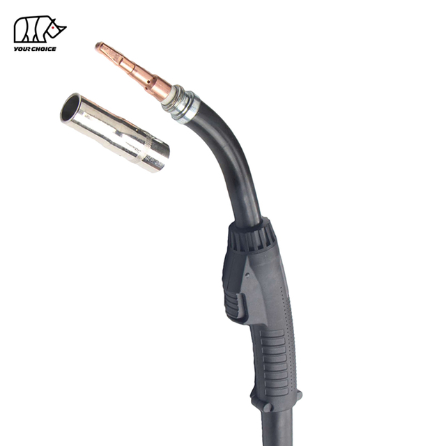
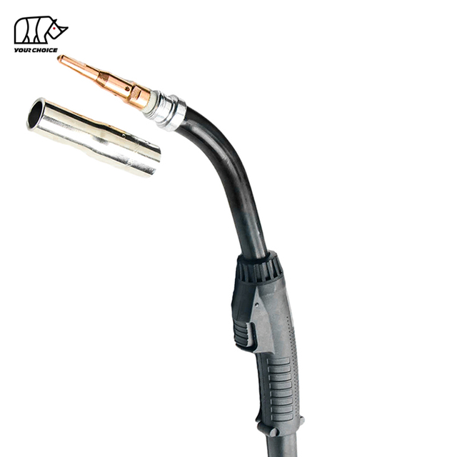
400A Air-Cooled MIG Welding Torch for Industrial Fabrication
The INWELT TR400 is an air-cooled MIG/MAG welding torch designed for professional manufacturing, structural fabrication, machinery production, maintenance and heavy-duty manual welding.
The current INWELT configuration is rated at 400A with CO₂ and 300A with mixed shielding gas at a 60% duty cycle and supports welding wire from Ø1.0 mm to Ø1.6 mm.
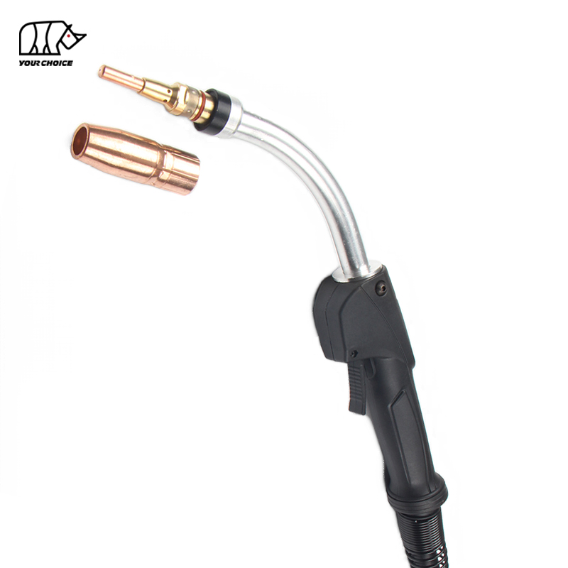
The TR400 uses a modular front-end system with replaceable contact tips, gas nozzles, gas diffuser, nozzle retainer, neck insulator and wire liner components.
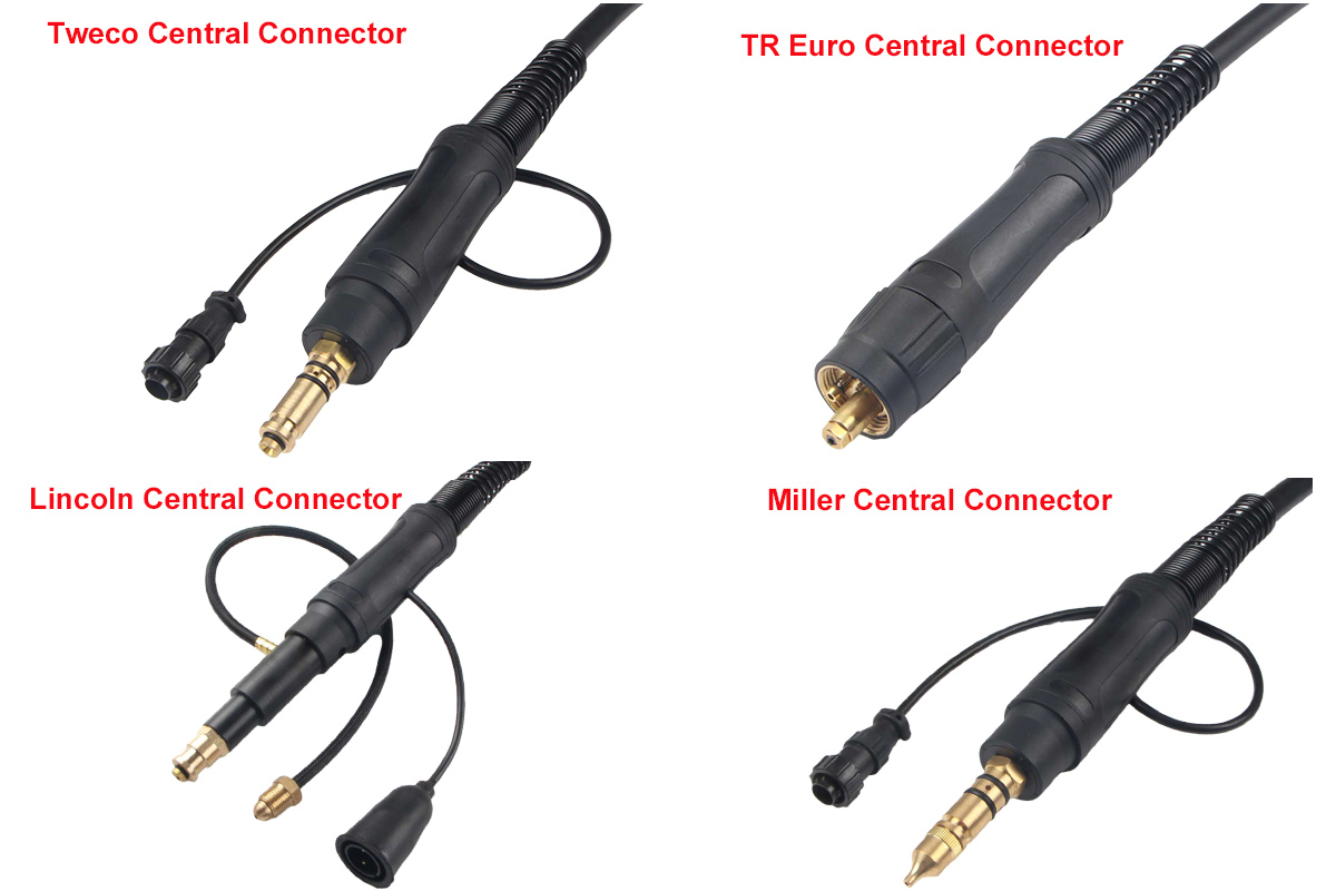
Two swan-neck angles—45° and 60°—are available for different joint-access requirements, while Euro, Miller, Lincoln and Tweco-style feeder connections allow the gun to be configured for multiple welding systems.
For welding equipment manufacturers, distributors and private-label brands, INWELT can also support OEM/ODM configurations, cable customization, consumable kits and customized packaging.
INWELT TR400 Technical Specifications
| Specification | INWELT TR400 |
| Product Type | Air-Cooled MIG/MAG Welding Torch |
| Model | TR400 |
| Brand | INWELT |
| Cooling | Air / Gas Cooled |
| Rated Current with CO₂ | 400 A |
| Rated Current with Mixed Gas | 300 A |
| Duty Cycle | 60% |
| Recommended Wire Range | Ø1.0–1.6 mm |
| Welding Process | MIG / MAG |
| Neck Options | 45° / 60° |
| Gas Diffuser Thread | 5/16-18 |
| Rear Connector Options | Euro / Miller / Lincoln / Tweco-style |
| Liner Options | According to wire diameter and gun length |
| Cable Length | Confirm required configuration before ordering |
| OEM / ODM | Available |
| Private Label | Available |
Before ordering, confirm the welding machine or feeder model, shielding gas, welding current, wire diameter, cable length and rear connection.
Why Choose the TR400 Air-Cooled MIG Gun?
The TR400 is designed for applications that require more welding capacity than a lighter 300A-class gun while retaining the simplicity of an air-cooled system.
400A CO₂ Welding Capacity
The current INWELT specification lists:
CO₂ and mixed shielding gases place different thermal loads on a MIG torch, so their ratings should always be shown separately.
Do not use the CO₂ rating as the mixed-gas rating.
Air-Cooled Construction
The TR400 does not require:
Coolant hoses
Water circulation
Welding cooler
Pump or radiator
This can simplify setup, servicing and torch replacement compared with a water-cooled welding gun.
For applications that consistently exceed the TR400's verified current or duty cycle, a higher-capacity or water-cooled torch may be more appropriate.
Ø1.0–1.6 mm Welding Wire Range
The verified INWELT product specification supports:
Ø1.0 mm
Ø1.2 mm
Ø1.4 mm
Ø1.6 mm
wire configurations when the correct contact tip and liner are installed.
The contact-tip list may include additional sizes for related consumable systems, but the TR400 product page should keep its primary operating range aligned with the verified Ø1.0–1.6 mm specification unless additional wire sizes are technically confirmed.
45° and 60° TR400 Swan Neck Options
Torch-neck geometry affects welding access, operator posture and joint visibility.
INWELT supplies the TR400 with both 45° and 60° swan-neck configurations.
45° TR400 Neck
The 45° neck provides a more open approach angle.
It can be suitable for:
60° TR400 Neck
The 60° neck provides a steeper approach angle.
It may improve access for:
Fillet welds
Corners
Frames
Restricted joints
Complex fabrication
Neither neck angle is universally better.
The correct choice depends on joint geometry, fixture design and operator preference.
TR400 Gas Nozzle Options
The TR400 consumable system includes multiple nozzle diameters and contact-tip positions.
Available nozzle designs currently include examples such as:
1/2 in. / 12.7 mm
5/8 in. / 15.9 mm
3/4 in. / 19 mm
with combinations including:
1/4 in. recess
1/8 in. recess
Flush
1/8 in. stick-out
Bottleneck
Copper
Brass
Recessed Nozzles
A recessed contact tip positions the tip farther inside the nozzle.
This configuration can be useful for higher-current spray-transfer or applications where additional front-end protection is desired.
Flush Nozzles
A flush configuration positions the contact tip close to the nozzle opening.
This can provide a different working distance and visibility depending on the welding procedure.
Stick-Out Nozzles
Stick-out configurations position the contact tip farther forward.
They may be useful where additional joint access is required.
Nozzle geometry should be selected according to the welding process, wire stickout, shielding-gas coverage and joint accessibility.
TR400 Contact Tips for MIG/MAG Welding
The contact tip transfers welding current from the torch to the continuously fed welding wire.
The TR400 parts system includes contact-tip sizes such as:
Ø1.0 mm / .040 in.
Ø1.2 mm / .045 in.
Ø1.4 mm / .052 in.
Ø1.6 mm / 1/16 in.
These sizes correspond to the verified TR400 welding-wire range.
The wider consumable catalog may also contain additional contact-tip sizes used in related torch systems.
Why Correct Contact-Tip Size Matters
A contact tip that is too tight can cause:
Feeding resistance
Burnback
Wire jamming
A heavily worn or oversized contact tip can contribute to:
Replace the contact tip based on actual wear and welding performance rather than a fixed number of welding hours.
TR400 Gas Diffuser, Nozzle Retainer and Neck Insulator
Gas Diffuser
The current TR400 parts system uses a 5/16-18 threaded gas diffuser.
The diffuser supports the contact tip and helps distribute shielding gas through the front of the torch.
Keep gas passages clean and replace the diffuser if threads become damaged or the component becomes excessively contaminated.
Nozzle Retainer
The nozzle-retaining component holds the gas nozzle in the intended position.
Inspect it when:
Neck Insulator
The neck insulator provides electrical isolation between appropriate torch components.
Replace it if it becomes:
Cracked
Burned
Mechanically damaged
Do not continue welding with damaged torch insulation.
TR400 Wire Liners and Feeding Performance
The liner guides welding wire through the gun cable from the feeder to the contact tip.
Current TR400 liner configurations include sizes for Ø1.2–1.6 mm wire and several gun lengths.
The correct liner should match:
Welding-wire diameter
Wire material
Gun length
Rear connector
Welding application
Why Liner Selection Matters
An undersized liner can create excessive feeding resistance.
A worn or contaminated liner can cause:
Current professional 400A MIG gun manufacturers similarly treat liner selection as a primary configuration variable rather than a minor accessory.
TR400 Euro, Miller, Lincoln and Tweco-Style Connections
The rear connection determines whether the MIG gun can correctly interface with the welding machine or wire feeder.
The INWELT TR400 product system includes configurations for:
Euro central connection
Miller-style connection
Lincoln-style connection
Tweco-style connection
Euro Central Connection
The Euro-style connection combines key welding-gun interfaces into a central connection widely used on MIG/MAG equipment.
Miller-Style Connection
A Miller-style rear connection can be supplied for compatible wire feeders.
Lincoln-Style Connection
Lincoln-style configurations use their corresponding feeder connection and control-wire arrangement.
Tweco-Style Connection
Tweco-style power-pin options are also available according to the target feeder.
Do not assume compatibility based only on torch amperage.
Always verify the welding machine or feeder model and rear connection.
For replacement orders, provide a photo of the existing connector when the interface is uncertain.
Is the INWELT TR400 Compatible with Tregaskiss MIG Guns?
The INWELT TR400 is designed as a Tregaskiss-style replacement MIG welding gun, but compatibility should be confirmed by specification rather than appearance or model name alone.
Check:
Rated current
Duty cycle
Wire diameter
Contact-tip family
Gas nozzle
Diffuser
Swan neck
Liner
Cable length
Power pin
Trigger/control lead
Wire feeder
Professional Tregaskiss/Bernard 400A air-cooled gun systems are themselves available with multiple neck, liner, consumable and power-pin combinations.
This is why a physically similar gun should not automatically be described as universally interchangeable.
When possible, provide the existing torch model or spare-part number before ordering.
TR400 vs. Typical 400A Tregaskiss-Style MIG Guns
The TR400 should be evaluated using its own verified INWELT specifications.
| Feature | INWELT TR400 |
| Cooling | Air Cooled |
| CO₂ Rating | 400A |
| Mixed-Gas Rating | 300A |
| Duty Cycle | 60% |
| Verified Wire Range | Ø1.0–1.6 mm |
| Neck Options | 45° / 60° |
| Connector Options | Euro / Miller / Lincoln / Tweco-style |
| Replaceable Consumables | Yes |
| OEM / Private Label | Available |
Other 400A-class MIG guns may publish different mixed-gas ratings, wire ranges or duty-cycle values.
Do not copy competitor amperage ratings onto the INWELT TR400.
Use INWELT's own tested electrical and thermal data consistently across the product page, catalog, technical sheet and structured data.
How to Choose the Correct TR400 Configuration
1. Confirm Welding Current
Identify the normal welding current used in production.
The torch should operate inside its verified current and duty-cycle range.
2. Confirm Shielding Gas
Specify whether the application uses:
The gas type affects the appropriate current rating.
3. Confirm Wire Diameter
Choose the correct liner and contact tip for the welding wire.
The verified TR400 range is Ø1.0–1.6 mm.
4. Select the Neck Angle
Choose 45° or 60° according to weld-joint geometry and working position.
5. Select the Gun Length
Use the shortest cable assembly that provides sufficient working reach.
Very long gun cables can add:
Weight
Drag
Feeding resistance
6. Confirm the Rear Connector
Specify whether the feeder requires:
Euro
Miller-style
Lincoln-style
Tweco-style
Providing the wire-feeder model is the most reliable method.
What Materials Can the TR400 MIG Torch Weld?
When combined with the correct filler wire, liner, contact tip, shielding gas and power source, the TR400 can be used for common professional MIG/MAG welding applications on materials such as:
Material compatibility depends on the complete welding procedure rather than the torch alone.
For specialized wire materials, confirm the correct liner and wire-feeding configuration before ordering.
Typical Applications for the TR400 MIG Welding Torch
The TR400 is designed for professional manual MIG/MAG welding where a 400A-class air-cooled gun matches the required duty cycle.
Typical applications include:
Structural steel fabrication
Heavy machinery manufacturing
Truck and trailer production
Agricultural equipment
Railway fabrication and repair
General industrial manufacturing
Construction equipment
Ship and marine fabrication
Industrial maintenance
Large steel assemblies
Production welding
Final gun selection should be based on current, duty cycle, shielding gas, wire size and feeder compatibility rather than industry name alone.
TR400 vs. TR300: When Do You Need More Capacity?
The TR400 provides additional welding capacity compared with a lower-rated TR300 platform.
Choose a TR400 when:
Normal welding current is higher
Longer arc-on time increases thermal load
Ø1.2–1.6 mm wire is commonly used
Heavy fabrication is the primary application
A lower-capacity torch may be preferable when:
The best torch balances electrical capacity with operator comfort and application requirements.
Air-Cooled vs. Water-Cooled MIG Torch
The TR400 is an air-cooled MIG welding torch.
Advantages of Air Cooling
An air-cooled system does not require:
Coolant hoses
Pump
Radiator
Welding cooler
This can reduce:
System complexity
Maintenance
Setup requirements
When to Consider Water Cooling
A water-cooled MIG torch may be more suitable where:
Welding current remains high for long periods
Arc-on time is very high
Production duty cycle exceeds air-cooled capacity
Front-end temperature becomes excessive
Operator heat exposure becomes uncomfortable
Torch selection should reflect actual production conditions rather than maximum amperage alone.
TR400 Maintenance and Consumable Inspection
Inspect the Contact Tip
Replace contact tips that are:
Enlarged
Burned
Heavily worn
Damaged by burnback
Clean the Gas Nozzle
Remove welding spatter before it blocks gas flow or bridges electrically between torch components.
Inspect the Gas Diffuser
Check:
Gas holes
Threads
Contact-tip seating
Replace damaged diffusers instead of overtightening the tip into worn threads.
Inspect the Wire Liner
Check the liner if wire feeding becomes inconsistent.
Dirt, wear and kinks can increase feeding resistance.
Inspect the Cable Assembly
Look for:
Cuts
Abrasion
Heat damage
Sharp kinks
Loose connections
Gas leakage
Avoid tightly coiling the cable during welding.
Product Parameters
| Position | Description |
| 1 | Swan Neck 45°; Swan Neck 60° |
| 2 | Torch Body Assembly |
| 3 | Handle |
| 4 | Switch |
| 5 | Switch The Trigger |
| 6 | End Fitting |
| 7 | Cone Nut |
| 8 | Cable Ball Joint & Support Spring Big |
| 9 | Cable Assembly |
| 10 | Euro Direct Plug Kit |
| 10-1 | Rear Handle |
| 10-2 | Adaptor nut |
| 10-3 | Euro Central Connector |
| 11 | Rear Handle American Brand |
| 12 | Control Wire (Tweco/Miller) |
| 12-1 | Control Wire (Lincoln) |
| 13 | Tweco Central Connector |
| 14 | Miller Central Connector |
| 15 | Lincoln Central Connector |
| 15-1 | Gas Tube |
|
|
| A | Nozzle 1/2″ 12.7mm 1/4″ Recess Copper |
| Nozzle 3/4” 19mm 1/4” Recess Copper |
| Nozzle 5/8” 15.9mm 1/4″ Recess Copper |
| Nozzle 1/2” 12.7mm 1/8” Recess Copper |
| Nozzle 5/8” 15.9mm 1/8” Recess Copper |
| Nozzle 3/4” 19mm 1/8” Recess Copper |
| Nozzle 5/8” 15.9mm 1/4” Recess Brass |
| Nozzle 3/4″ 19mm 1/8” Recess Brass |
| Nozzle 5/8″ 15.9mm 1/8” Recess Brass |
| Nozzle 5/8” 15.9mm Flush Bottleneck Copper |
| Nozzle 5/8” 15.9mm 1/8” Stick Out Brass |
| Nozzle 5/8” 15.9mm 1/8” Stick Out Copper |
| B | Contact Tip .030” 0.8mm |
| Contact Tip .035” 0.9mm |
| Contact Tip .040” 1.0mm |
| Contact Tip .045” 1.2mm |
| Contact Tip .052” 1.4mm |
| Contact Tip 1/16” 1.6mm |
| Contact Tip .078″ 2.0 mm |
| Contact Tip 3/32″ 2.4 mm |
| C | Gas Diffuser (5/16-18Thd) |
| D | Nozzle Retainer |
| E | Neck Insulator |
| F | Liner for .045″-1/16″(1.2-1.6mm) 10FT(3.0m) |
| Liner for .045″-1/16″(1.2-1.6mm) 15FT(4.6m) |
| Liner for .045″-1/16″(1.2-1.6mm) 25FT(7.6m) |
|
|
| Technical Data | Rating: 400A CO2/300A Mixed Gases |
| Duty Cycle: 60% |
| Wire Size: 040”-1/16”(1.0-1.6mm) |
| Type | TR400 MIG GUN Miller Connector |
| TR400 MIG GUN Tweco Connector |
| TR400 MIG GUN Lincoln Connector |
| TR400 MIG GUN Euro Connector |
Multiple Options for Rear Connectors
Our Catalog:
 INWELT MIG WELDING TORCH.pdf
Common TR400 MIG Welding Problems
Irregular Wire Feeding
Check:
Drive-roll condition
Drive-roll pressure
Liner
Contact-tip size
Cable bends
Wire condition
Contact Tip Overheating
Possible causes include:
Excessive Spatter
Check:
Voltage
Wire-feed speed
Shielding gas
Contact-tip condition
Torch angle
Workpiece condition
Poor Gas Coverage
Inspect:
Gas nozzle
Diffuser
Gas hose
Rear connection
Flow setting
Spatter buildup
Gun Overheating
Check:
Welding current
Mixed-gas vs. CO₂ rating
Arc-on time
Duty cycle
Cable condition
Electrical connections
If the gun repeatedly overheats under normal production conditions, consider moving to a higher-capacity or water-cooled platform.
TR400 Consumables for Distributor and Aftermarket Supply
For welding distributors, the complete torch is only part of the long-term product opportunity.
A TR400 aftermarket program can include:
Contact tips
Gas nozzles
Gas diffusers
Nozzle retainers
Neck insulators
Wire liners
Swan necks
Handles
Trigger switches
Cable assemblies
Rear connectors
Supplying both complete guns and replacement consumables helps distributors support customers throughout the service life of the product.
It also simplifies repeat orders when parts are clearly identified by size and configuration.
OEM Tregaskiss-Style MIG Gun Manufacturing by INWELT
INWELT supplies MIG/MAG welding guns and replacement components to professional B2B customers including:
OEM and ODM projects can be configured according to machine interface, target market and purchasing requirements.
OEM and Private-Label Options
Customization may include:
For OEM projects, provide the welding machine or wire feeder, welding-current range, shielding gas, wire diameter, connector and expected order volume.
Why Source TR400 MIG Guns from INWELT?
INWELT supplies complete welding torches together with corresponding replacement components.
For professional B2B buyers, this can simplify:
Torch sourcing
Consumable sourcing
Compatibility management
Spare-parts stocking
Private-label projects
Aftermarket service
The TR400 platform provides multiple neck, nozzle and rear-connection configurations, allowing distributors to support different welding systems through one product family.
Frequently Asked Questions About the TR400 MIG Welding Torch
Is the TR400 air cooled?
Yes.
The INWELT TR400 is an air-cooled MIG/MAG welding torch and does not require an external liquid-cooling system.
What is the TR400 amperage rating?
The current INWELT specification lists:
400A with CO₂
and
300A with mixed shielding gas
at a 60% duty cycle.
Why are the CO₂ and mixed-gas ratings different?
Different shielding gases influence thermal load differently.
For this reason, MIG gun ratings should identify both the gas and the duty cycle.
What welding wire does the TR400 support?
The verified INWELT specification supports Ø1.0–1.6 mm welding wire.
What neck angles are available?
The TR400 is available with 45° and 60° swan-neck configurations.
What rear connectors are available?
Available configurations include:
Euro
Miller-style
Lincoln-style
Tweco-style
Confirm the wire-feeder model before ordering.
Is the TR400 a genuine Tregaskiss gun?
No.
The TR400 is an INWELT-manufactured Tregaskiss-style replacement welding gun.
It should not be represented as a genuine or authorized Tregaskiss-manufactured product.
Will the TR400 fit any 400A MIG welder?
No.
Gun amperage alone does not determine compatibility.
The rear connection, trigger wiring, power pin, wire size and feeder interface must also match.
Are Tregaskiss-style consumables compatible with the TR400?
Selected Tregaskiss-style consumable dimensions may be compatible, but each component should be checked by thread, size and configuration before substitution.
What gas diffuser does the TR400 use?
The current INWELT parts list specifies a 5/16-18 threaded gas diffuser.
What wire liner does the TR400 use?
The liner should be selected according to wire diameter and gun length.
Current INWELT configurations include liners for Ø1.2–1.6 mm wire.
Can the TR400 weld stainless steel?
Yes, when the complete welding system uses appropriate stainless filler wire, shielding gas, liner and welding parameters.
Can the TR400 weld aluminum?
A suitable configuration may be possible, but soft aluminum wire requires the correct liner, feeder, contact tip and gun setup.
Confirm the application before ordering.
How often should TR400 contact tips be replaced?
There is no universal replacement interval.
Replace the tip when wear causes poor electrical contact, unstable feeding, arc problems or excessive burnback.
Does INWELT offer OEM TR400 welding guns?
Yes.
OEM/ODM, private-label, connector, cable, neck and packaging configurations are available for qualified B2B customers.
Request a Quote for the INWELT TR400 MIG Welding Torch
For faster configuration confirmation, provide:
Welding machine or feeder brand and model
Required welding current
CO₂ or mixed shielding gas
Welding-wire diameter
Required gun length
45° or 60° neck
Rear connector
Consumable requirements
Estimated order quantity
INWELT or private-label branding
INWELT can then recommend the appropriate TR400 torch and consumable configuration for your MIG/MAG welding system.
 English
 简体中文
简体中文 العربية
 Français
 Русский
 Español
 Português
 Deutsch
 italiano
 日本語
日本語 한국어
한국어 Nederlands
 Tiếng Việt
 ไทย
ไทย Polski
 Türkçe
 ភាសាខ្មែរ
 Bahasa Melayu
 Filipino
 Bahasa Indonesia
 magyar
 Română
 Čeština
 Монгол
 қазақ
қазақ Српски
 हिन्दी
 فارسی
فارسی Slovenčina
 Slovenščina
 Norsk
Norsk Svenska
 українська
 Ελληνικά
 Suomi
Suomi Latine
 Dansk
Dansk বাংলা
বাংলা Hrvatski
 Afrikaans
 Gaeilge
 Eesti keel
 नेपाली
 Oʻzbekcha
 latviešu
 Azərbaycan dili
 Беларуская мова
 Bosanski
 Български
 ქართული
 Lietuvių