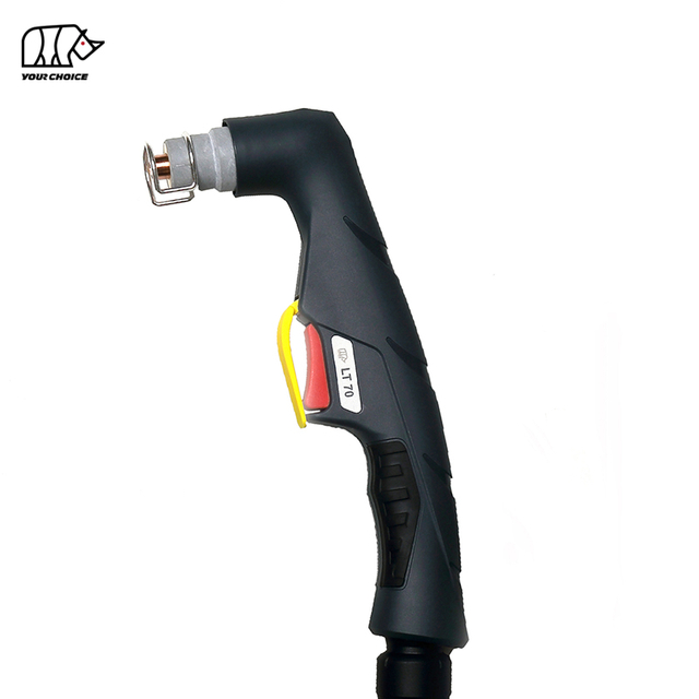
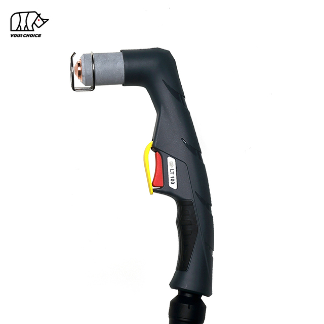
80A HF CNC Plasma Cutting Torch for Mechanized Cutting
The INWELT LTM81 is an air-cooled CNC and mechanized plasma cutting torch designed for automated plasma tables, profile-cutting machines and industrial metal-cutting systems.
The LTM81 is rated at 80A with a 60% duty cycle and uses a high-frequency (HF) arc-starting system.
The current INWELT technical configuration includes:
80A rated current
60% duty cycle
Compressed-air operation
HF arc starting
Approx. 4.5–5.0 bar operating pressure
Approx. 160 L/min airflow
Approx. 80-second recommended post-flow
Standard 6 m torch lead
CNC / mechanized operation
Multiple machine-torch connection options are available, including:
3/8G
1/4G
M14×1
M16×1.5
Central adapter
The LTM81 should be positioned specifically as a machine/CNC plasma torch, separate from the LT81 handheld plasma torch.
INWELT LTM81 Technical Specifications
| Specification | INWELT LTM81 |
| Product Type | CNC / Mechanized Plasma Cutting Torch |
| Model | LTM81 |
| Brand | INWELT |
| Rated Current | 80 A |
| Duty Cycle | 60% |
| Cooling | Air |
| Process Gas | Compressed Air |
| Arc Starting | HF |
| Gas Pressure | Approx. 4.5–5.0 bar |
| Gas Flow | Approx. 160 L/min |
| Recommended Post-Flow | Approx. 80 seconds |
| Standard Lead Length | 6 m |
| Operation | CNC / Mechanized |
| Connector Options | 3/8G / 1/4G / M14×1 / M16×1.5 / Central Adapter |
| Standard Tip Sizes | Ø1.0 / Ø1.1 / Ø1.2 mm |
| Extended Tips | Available |
| OEM / ODM | Available |
| Private Label | Available |
Before ordering, confirm the plasma power source, rated current, HF starting architecture, pilot-arc circuit, rear connector, control interface and CNC system requirements.
LTM81 vs. LT81: Machine Torch vs. Hand Torch
The LTM81 and LT81 belong to the same broader torch and consumable family, but they should be treated as two separate complete products.
| Feature | LTM81 | LT81 |
| Operation | CNC / Mechanized | Manual / Handheld |
| Torch Geometry | Straight machine torch | Angled hand torch |
| Start Control | Machine controlled | Operator trigger |
| Mounting | Fixed torch holder | Handheld |
| Torch Height | CNC / THC controlled | Operator controlled |
| Primary Application | Automated cutting | Manual cutting |
Some consumables may be shared between the two configurations.
However, the complete torch head, body, positioning tube, cable assembly and control arrangement should not automatically be treated as interchangeable.
For internal website links, use:
LTM81 CNC Plasma Cutting Torch
and
LT81 Manual Plasma Cutting Torch
rather than describing both products simply as A81- or LT81-type torches.
Why Use a Dedicated 80A Machine Torch for CNC Plasma Cutting?
A CNC plasma cutting system requires a torch designed for stable machine mounting and repeatable automated operation.
Straight Machine-Torch Geometry
The LTM81 uses a machine-oriented torch structure that can be mounted on a CNC Z-axis or dedicated torch holder.
Correct installation helps maintain:
Torch perpendicularity
Repeatable pierce position
Consistent cutting height
Stable kerf geometry
Repeatable part dimensions
Machine-Controlled Cutting Cycle
Unlike a handheld torch, the LTM81 is controlled through the plasma power source and CNC system.
A typical mechanized cutting cycle can include:
Torch positioning
Initial-height sensing
Plasma start command
Piercing
Cutting movement
Torch-height adjustment
Arc stop
Repeatable Production
A fixed machine torch allows cutting conditions to be controlled more consistently across repeated parts when the plasma power source, gas supply, CNC motion and consumables are correctly configured.
How the LTM81 HF Plasma Cutting System Works
The LTM81 operates as one component of a complete plasma cutting system consisting of:
Compressed air flows through the torch head, diffuser, electrode and cutting tip.
Electrical energy ionizes the gas and produces a high-temperature plasma arc.
The cutting nozzle constricts the plasma stream into a concentrated jet that melts electrically conductive material while high-velocity gas removes molten metal from the kerf.
How HF Arc Starting Works on the LTM81
The LTM81 uses a high-frequency arc-starting system.
HF ignition uses a high-frequency electrical signal to assist in establishing the initial plasma arc.
The plasma power source must therefore be designed for a compatible HF torch architecture.
HF, non-HF and back-striking plasma torches should not be selected interchangeably based only on amperage or connector appearance.
HF Installation Considerations for CNC Systems
Because HF starting generates high-frequency electrical energy, the complete CNC installation should follow the plasma power-source manufacturer's requirements for:
Grounding
Work connection
CNC cable routing
Signal-cable separation
Controller installation
Torch lead routing
Do not assume that an HF torch can be connected to any CNC controller without considering the complete machine electrical architecture.
LTM81 Complete Machine Torch Configurations
The current INWELT product family includes several 6 m LTM81 machine-torch assemblies.
| INWELT Code | Configuration |
| IJWU0641 | LTM81 / 6 m / 3/8G |
| IJWU0647 | LTM81 / 6 m / Central Adapter |
| IJWU0717 | LTM81 / 6 m / 1/4G |
| IJWU0718 | LTM81 / 6 m / M16×1.5 |
| IJWU0719 | LTM81 / 6 m / M14×1 |
These complete-torch codes should be shown prominently on the product page because connection type is a major selection factor for replacement and OEM machine torches.
The LT81 hand-torch assemblies should be moved to the corresponding manual-torch page or clearly labeled as related products.
LTM81 Machine Torch Head
The dedicated LTM81 machine torch head is:
INWELT Code: IJWA0681
Reference: PF0120
Description:
LTM81 Machine Plasma Torch Head
This machine-specific torch head should be one of the primary components displayed on the LTM81 product page.
It should not be replaced in the main product diagram by the LT81 handheld torch head.
LTM81 Fiberglass Positioning Tube
The current machine-torch system includes:
INWELT Code: IJHW0029
Reference: W0300144
Description:
Fiberglass Positioning Tube / LTM
The positioning tube forms part of the straight machine-torch structure and should be shown together with the machine torch head.
For CNC equipment manufacturers, this component is especially relevant to torch mounting and integration.
Add an LTM81 Machine-Torch Dimension Drawing
For a CNC machine torch, physical dimensions are important purchasing information.
INWELT should add a technical drawing showing the actual production dimensions of the LTM81, including:
Do not copy another supplier's machine-torch dimensions.
Measure the actual INWELT LTM81 and publish first-party dimensional data.
This information is particularly useful for:
LTM81 Standard Cutting Tips
The current LTM81/LT81 consumable platform includes three primary standard cutting-tip diameters.
Ø1.0 mm Cutting Tip
INWELT Code: IJWV0616-10
Reference: PD0105-10
Ø1.1 mm Cutting Tip
INWELT Code: IJWV0616-11
Reference: PD0105-11
Ø1.2 mm Cutting Tip
INWELT Code: IJWV0616-12
Reference: PD0105-12
Different tip diameters are intended for different operating-current ranges and cutting processes.
Before publishing a final amperage-to-nozzle table, verify the INWELT current mapping against current engineering data, ERP records and cutting tests.
Do not infer the full torch rating simply from the nozzle diameter.
Which Cutting Tip Should Be Used at 80A?
The current INWELT consumable family includes Ø1.0 mm, Ø1.1 mm and Ø1.2 mm cutting tips.
Comparable A81-type plasma systems commonly use the largest standard nozzle in this family for the upper 80A operating range.
However, INWELT should publish its own verified mapping.
The strongest final table would include:
| INWELT Code | Tip Diameter | Verified Current | Electrode | Diffuser | Cutting Mode |
| IJWV0616-10 | Ø1.0 mm | Verify | Matching Part | Matching Part | Standard Cutting |
| IJWV0616-11 | Ø1.1 mm | Verify | Matching Part | Matching Part | Standard Cutting |
| IJWV0616-12 | Ø1.2 mm | Verify | Matching Part | Matching Part | Standard Cutting |
Once verified, use the same current mapping consistently in the product page, catalog, ERP system and technical drawings.
LTM81 Extended Cutting Tips
The current consumable family also includes extended cutting tips.
Extended Ø1.0 mm Tip
INWELT Code: IJWV0612-10
Reference: PD0106-10
Extended Ø1.2 mm Tip
INWELT Code: IJWV0612-12
Reference: PD0106-12
Extended tips provide additional reach when the standard front end cannot access a recessed cutting location.
For CNC use, an extended tip changes the torch-front geometry.
The CNC cutting height and consumable stack should therefore be verified before using an extended configuration.
LTM81 Plasma Electrode
The standard electrode listed for the LT81/LTM81 family is:
INWELT Code: IJWC0615
Reference: PR0109
The electrode transfers electrical energy through the plasma torch and gradually wears during repeated arc starts and cutting.
Replace the electrode before excessive wear causes:
Difficult arc starting
Arc instability
Accelerated nozzle wear
Inconsistent CNC cutting
For automated production, electrode condition should be inspected regularly because repeated piercing cycles can increase consumable wear.
Verify the Extended Electrode and Air-Tube Codes Before Publishing
The current product page contains extended-electrode and air-tube references, but several descriptions appear inconsistent.
Before publishing an authoritative consumable table, verify the exact INWELT mapping for:
PR0115
FH0560
FH0561
Extended electrode
Standard air tube
Extended air tube
Once confirmed, publish each component as:
INWELT Code → Reference → Component Type → Standard/Extended → Compatible Tip
This will reduce replacement-part errors and improve the technical value of the page.
LTM81 Gas Diffuser
The current diffuser is:
INWELT Code: IJWG0613
Reference: PE0107
The diffuser controls process-gas distribution around the electrode and cutting nozzle.
Correct airflow contributes to:
Stable plasma-arc formation
Consumable cooling
Consistent plasma-jet shape
Repeatable cutting performance
Replace the diffuser if it becomes:
Cracked
Burned
Distorted
Contaminated
Do not modify or enlarge the gas passages.
LTM81 Outside Nozzle Options
The current consumable family includes:
IJWT0676-03 / PC0115 – Outside Nozzle
and
IJWT0676-01 – Maximum-Life Outside Nozzle
The outside nozzle helps position and protect the front-end consumable stack.
Replace it if it becomes cracked, burned or mechanically damaged.
For a CNC application, make sure the outside-nozzle configuration matches the selected cutting tip and stand-off arrangement.
LTM81 Stand-Off and Contact-Cutting Accessories
The current product family includes several front-end positioning accessories.
Examples include:
IJTN0717 / CV0201 – Spacer for Contact Cutting
IJTN0099 / CV0033 – Four-Point Spacer
IJTN0084 / CV0028 – Spacer Spring
These components help control the relationship between the nozzle and the workpiece.
For mechanized cutting, the cutting process should be selected according to the plasma power source, consumable configuration and CNC height-control method.
LTM81 Machine Cable Assemblies
The current LTM81 machine-torch family includes dedicated 6 m cable assemblies.
1/8G Machine Cable
INWELT Code: IJWO10108077-00
Description:
LTM81 / 8 mm² / 6 m / 1/8G
Central-Adapter Machine Cable
INWELT Code: IJWO10108071-00
Description:
LTM81 / 8 mm² / 6 m / Central Adapter
Keep these machine cables in the primary LTM81 parts table.
LT81 handheld cable assemblies should instead be placed on the manual LT81 page.
LTM81 Connector Adapter Options
The LTM81 system includes multiple connection adapters.
1/8G to 1/4G
INWELT Code: IJAU5698
1/8G to 3/8G
INWELT Code: IJAU5697
1/8G to M14×1
INWELT Code: IJAU5699
1/8G to M16×1.5
INWELT Code: IJAU5690
These adapter options allow different power-source connections to be evaluated without treating every physical connector as a universally compatible system.
LTM81 5-Pin Central Adapter
The current product family also includes:
INWELT Code: IJAY0089
Reference: FY0023
Description:
5-Pin Plasma Torch-Side Central Adapter
A central adapter can simplify torch installation on compatible plasma systems.
However, physical connector fit alone does not confirm electrical compatibility.
The following must also be verified:
Pin functions
Pilot-arc circuit
Start/control signals
Power connection
Gas connection
How to Check LTM81 CNC Plasma Cutter Compatibility
Do not select the LTM81 only because the machine is labeled “80A.”
Several technical conditions must match.
Confirm HF Starting
The plasma power source must support a compatible HF machine torch.
Confirm Rated Current
The LTM81 is rated at 80A.
The torch and consumables should be operated within their verified current range.
Confirm the Rear Connection
Available complete-torch configurations include:
3/8G
1/4G
M14×1
M16×1.5
Central adapter
Confirm the Pilot-Arc Circuit
Different plasma power sources can use different pilot-arc arrangements.
Confirm the Start and Control Interface
The machine's plasma-start circuit must match the torch and power-source architecture.
Provide Machine Information Before Ordering
For replacement or OEM projects, provide:
Plasma power-source manufacturer
Machine model
Rated output current
Existing torch model
Main connector photographs
Pilot-arc connector photographs
CNC controller information
Required torch mounting dimensions
This is more reliable than publishing a universal list of plasma-cutter brands.
Spare Parts Details:
| HAND TORCH |
| Code | Ref. | Description |
| IJWU6911 | PA1400 | Plasma cutting torch LT81/6m 3/8G |
| IJWU6912 |
| Plasma cutting torch LT81/6m M14×1 |
| IJWU6916 |
| Plasma cutting torch LT81/6m M16×1.5 |
| IJWU6918 | PA1402 | Plasma cutting torch LT81/6m central adaptor |
| IJWU6910 | PA1404 | Plasma cutting torch LT81/6m 1/4G |
| MACHINE TORCH |
|
|
| Code | Ref. | Description |
| IJWU0641 |
| Plasma cutting auto torch LTM81/6m 3/8G |
| IJWU0647 |
| Plasma cutting auto torch LTM81/6m central adaptor |
| IJWU0717 |
| Plasma cutting auto torch LTM81/6m 1/4G |
| IJWU0718 |
| Plasma cutting auto torch LTM81/6mM16×1.5 |
| IJWU0719 |
| Plasma cutting auto torch LTM81/6mM14×1 |
| Position | Code | Ref. | Description |
| 1 | IJTN0717 | CV0201 | Spacer for contact cutting/LT81 |
| 2 | IJTN0099 | CV0033 | Four point edspacer/LT81 |
| 3 | IJTN0084 | CV0028 | Spacer spring LT81 |
| 4 |
|
| Outside nozzle |
| 4.1 | IJWT0676-03 | PC0115 | Outside nozzle LT81 |
| 4.2 | IJWT0676-01 |
| Outside nozzle/maximum life LT81 |
| 5 |
|
| Tip |
| 5.1 | IJWV0616-10 | PD0105-10 | Tip Φ1.0mm LT81 |
| 5.2 | IJWV0616-11 | PD0105-11 | Tip Φ1.1mm LT81 |
| 5.3 | IJWV0616-12 | PD0105-12 | Tip Φ1.2mm LT81 |
| 6 |
|
| Tip |
| 6.1 | IJWV0612-10 | PD0106-10 | Extended tip Φ1.0mmLT81 |
| 6.2 | IJWV0612-12 | PD0106-12 | Extended tip Φ1.2mmLT81 |
| 7 | IJWG0613 | PE0107 | Diffuser LT81 |
| 8 | IJWC0615 | PR0109 | Electrode Plasma LT81 |
| 9 | IJWC0676 | PR0115 | Airtube/LT81 |
| 10 | IJAO0521 | FH0560 | Extended electrode PlasmaLT81 |
| 11 | IJAO0527 | FH0561 | Extended airtube/LT81 |
| 12 | IJWA0601 |
| Plasma torch head LT81 |
| 12a | IJGU0686 | EA0125 | “O”ring Φ15.6x1.78mm in silicon |
| 13 | IJHW0046 |
| Plasma hand lemanual/ASeries/Red |
| 14 | IJIK0733 |
| Protection part/Plasma/Yellow |
| 15 | IJIR0081 | 185.0031 | Trigger |
| 16 | IJIK0804 |
| Joint/small/new type |
| 17 |
|
| Cable assembly |
| 17.1 | IJWO00108077-00 |
| Cable assembly/LT81/8MMQ/6MATT.1/8G |
| 17.2 | IJWO00108071-00 |
| Cable assembly/LT81/8MMQ/6MCENTERADAPTOR |
| 17.3 | IJWO10108077-00 |
| Cable assembly/LTM81/8MMQ/6MATT.1/8G |
| 17.4 | IJWO10108071-00 |
| Cable assembly/LTM81/8MMQ/6MCENTERADAPTOR |
| 17.5 | IJWO0690 |
| Cable assembly/LT81/6 mcentral adaptor |
| 18 | IJDH6017 |
| Spanner for Plasma |
| 19 | IJWA0681 | PF0120 | Plasma torch head LTM81 |
| 19a | IJHW0029 | W0300144 | Fiber glass position tube/LTM |
| 20 |
|
| Cable assembly LTM |
| 20.1 | IAU5698 |
| Connecting adaptor 1/8G-1/4G |
| 20.2 | IJAU5697 |
| Connecting adaptor 1/8G-3/8G |
| 20.3 | IJAU5699 |
| Connecting adaptor 1/8G-M14×1 |
| 20.4 | IJAU5690 |
| Connecting adaptor 1/8G-M16×1.5 |
| 21 IJAY0089 FY0023 Central adaptor torch side Plasma 5pins |
| 22 IJTN0067 CV0052 Wheel space RA81/S75 |
Our Catalog:
 INWELT PLASMA TORCH CATALOG.pdf
LTM81 and CNC Torch Height Control
A CNC plasma system may use automatic torch-height control to maintain the intended torch-to-work distance.
Possible systems include:
Arc-Voltage Torch Height Control
During cutting, a compatible THC can use arc voltage as part of maintaining the programmed torch height.
The correct target voltage depends on the complete plasma power source, consumables, material, current and cutting speed.
HF and THC Integration
Because the LTM81 uses HF ignition, the CNC and THC installation should follow the plasma power-source manufacturer's grounding and electrical-layout requirements.
Do not publish a universal THC voltage or wiring arrangement unless it has been verified for the actual INWELT-compatible system.
Piercing Height vs. Cutting Height
CNC plasma cutting normally uses different heights during piercing and continuous cutting.
Piercing Height
During piercing, molten metal is expelled upward from the workpiece.
Correct pierce height helps reduce damage to the nozzle and other front-end consumables.
Cutting Height
After the pierce is complete, the CNC system moves to the programmed cutting height.
Incorrect cutting height can contribute to:
Use tested values from the complete plasma system.
How Thick Can the LTM81 Cut?
The plasma torch alone does not determine one universal maximum cutting thickness.
Actual cutting capacity depends on:
Plasma power source
Input power
Material
Cutting current
Cutting-tip diameter
Air pressure
Airflow
Travel speed
Piercing height
Cutting height
Consumable condition
Required edge quality
Professional plasma specifications should distinguish between three performance levels.
Recommended Cutting Capacity
Material thickness that can be cut productively with suitable speed and edge quality.
Maximum Cutting Capacity
Thicker material that can still be cut at reduced speed.
Severance Capacity
The maximum thickness that can be separated, usually with lower edge quality.
Specific LTM81 cutting-thickness figures should therefore be published only when supported by an INWELT complete-system test.
Build an INWELT LTM81 CNC Cut Chart
A first-party LTM81 cutting chart would be one of the strongest technical and GEO assets for this page.
Recommended data fields include:
| Parameter | Data to Publish |
| Material | Mild Steel / Stainless Steel / Aluminum |
| Thickness | Tested thickness |
| Current | Actual tested current |
| Tip Code | INWELT part number |
| Tip Diameter | mm |
| Air Pressure | bar |
| Air Flow | L/min |
| Travel Speed | mm/min |
| Pierce Height | mm |
| Pierce Delay | seconds |
| Cutting Height | mm |
| Kerf Width | mm |
| Cut Result | Recommended / Maximum / Severance |
Use measured INWELT test results rather than copying another manufacturer's cutting data.
Recommended Air Supply for the LTM81
The current INWELT LTM81 configuration uses compressed air.
Recommended operating data includes:
Gas: Compressed Air
Gas Pressure: Approx. 4.5–5.0 bar
Gas Flow: Approx. 160 L/min
Recommended Post-Flow: Approx. 80 seconds
Use Clean and Dry Compressed Air
Moisture, compressor oil and particles can negatively affect:
Arc stability
Electrode life
Cutting-tip life
Cut consistency
Use suitable filtration and moisture separation.
Check Pressure Under Flow
Static regulator pressure can differ from operating pressure while the torch is flowing air.
Filters, regulators, fittings and long air lines can create pressure loss.
Set the air supply according to the complete plasma system's operating procedure.
What Materials Can the LTM81 Cut?
When connected to a compatible plasma cutting system, the LTM81 can cut electrically conductive materials including:
Mild steel
Carbon steel
Stainless steel
Aluminum
Copper
Brass
Galvanized steel
Actual cutting speed, edge quality and practical thickness depend on the complete plasma cutting system.
Typical Applications for the LTM81 CNC Torch
The LTM81 is designed for mechanized plasma cutting applications including:
CNC plasma cutting tables
Automated profile cutting
Sheet-metal fabrication
Structural fabrication
Machinery components
Agricultural equipment parts
Automotive components
Construction equipment parts
Metal furniture
Sign fabrication
General industrial production
Automated metal-cutting cells
Robotic-arm applications should be promoted only when the mounting arrangement, cable routing, torch collision protection and control interface have been verified for that system.
LTM81 Maintenance for CNC Production
Consistent consumable condition is important in automated cutting because a worn component can affect every repeated part.
Inspect the Electrode
Check the electrode regularly for excessive wear.
Replace it before severe erosion causes unreliable starting or damages the nozzle.
Inspect the Cutting Tip
Check for:
Enlarged nozzle opening
Oval orifice
Burn damage
Heavy contamination
A worn nozzle can affect:
Inspect the Diffuser
Keep gas passages clean.
Replace cracked or heat-damaged components.
Inspect the Outside Nozzle
Check the insulating component for cracks and thermal damage.
Inspect the Machine Torch Head
Check:
Threads
Sealing surfaces
O-ring condition
Gas leakage
Heat damage
Inspect the Torch Lead
Make sure CNC movement does not:
Common LTM81 CNC Cutting Problems
Difficult HF Arc Starting
Check:
Electrode condition
Cutting tip
HF starting circuit
Gas pressure
Work connection
Torch connection
Excessive Bevel
Check:
Torch perpendicularity
Cutting height
Nozzle condition
Travel speed
Heavy Dross
Check:
Cutting speed
Cutting current
Material thickness
Airflow
Torch height
Short Consumable Life
Possible causes include:
Inconsistent Part Dimensions
Inspect:
Torch mounting
Cutting height
Kerf compensation
CNC backlash
Consumable condition
Cutting speed
Not every dimensional problem is caused by the plasma torch.
LTM81 Consumables for Distributor and Aftermarket Supply
A professional LTM81 aftermarket program can include:
For distributors and CNC machine manufacturers, publishing exact INWELT part numbers helps reduce replacement errors and supports repeat purchasing.
OEM LTM81 CNC Plasma Torch Manufacturing by INWELT
INWELT supplies plasma cutting torches and replacement components to professional B2B customers including:
CNC plasma machine manufacturers
Plasma power-source manufacturers
CNC system integrators
Welding and cutting equipment brands
Importers
Distributors
Wholesalers
Industrial suppliers
Aftermarket consumable companies
OEM and ODM configurations can be evaluated according to the target plasma system and machine interface.
OEM and Private-Label Options
Customization may include:
For OEM projects, provide the plasma power-source specification, CNC controller, connector arrangement, mounting requirements and estimated purchasing quantity.
Why Source LTM81 Machine Torches from INWELT?
The LTM81 platform combines complete machine-torch assemblies with a detailed consumable, cable and connector system.
The current product family includes:
Multiple complete 6 m machine-torch configurations
Ø1.0 / Ø1.1 / Ø1.2 mm standard tips
Extended cutting tips
Standard electrode
Diffuser
Outside nozzles
Dedicated LTM81 machine torch head
Fiberglass positioning tube
Machine cable assemblies
Multiple thread adapters
5-pin central adapter
For professional buyers, sourcing the complete machine torch and replacement parts through one supplier can simplify purchasing, inventory and aftermarket support.
Frequently Asked Questions About the LTM81 CNC Plasma Torch
What amperage is the INWELT LTM81?
The LTM81 is rated at 80A according to the current INWELT technical specification.
What is the LTM81 duty cycle?
The current specification lists a 60% duty cycle.
Is the LTM81 a hand torch or machine torch?
The LTM81 is a CNC / mechanized machine torch.
The related LT81 is the manual handheld configuration.
Does the LTM81 use HF ignition?
Yes.
The LTM81 uses high-frequency arc starting.
What gas does the LTM81 use?
The current configuration uses compressed air.
What air pressure does the LTM81 require?
Approximately 4.5–5.0 bar.
What airflow does the LTM81 require?
The current INWELT specification lists approximately 160 L/min.
What post-flow time is recommended?
Approximately 80 seconds.
What torch lead length is standard?
The standard LTM81 lead is 6 m.
What connector options are available?
The current machine-torch range includes:
3/8G
1/4G
M14×1
M16×1.5
Central adapter
What cutting-tip sizes are available?
The current consumable family includes:
Extended Ø1.0 mm and Ø1.2 mm tips are also available.
Which electrode does the LTM81 use?
The current standard electrode is:
IJWC0615 / PR0109
Verify the exact extended-electrode and air-tube part-number mapping before publishing those components as authoritative data.
What machine torch head does the LTM81 use?
The current INWELT machine head is:
IJWA0681 / PF0120
What positioning tube does the LTM81 use?
The current product family lists:
IJHW0029 / W0300144 – Fiberglass Positioning Tube
Is the LTM81 compatible with every 80A CNC plasma cutter?
No.
The HF starting system, pilot-arc architecture, connector, control interface, gas requirements and plasma power source must also match.
Does the LTM81 support torch-height control?
It can be integrated into CNC systems using compatible torch-height-control equipment.
The exact THC configuration depends on the plasma power source and CNC controller.
Can the LTM81 cut stainless steel?
Yes, when used with a compatible plasma system and suitable operating parameters.
Can the LTM81 cut aluminum?
Yes.
Aluminum is electrically conductive and can be plasma cut with an appropriate plasma system.
How thick can the LTM81 cut?
There is no universal thickness determined by the torch alone.
Use verified recommended, maximum and severance data from the complete plasma cutting system.
Can the LTM81 be installed on a robotic arm?
Potentially, but robotic integration should only be confirmed after checking the mounting arrangement, cable routing, control interface and collision-protection requirements.
What is the difference between LTM81 and LT81?
LTM81 is the machine/CNC version.
LT81 is the manual/handheld version.
Does INWELT offer OEM LTM81 machine torches?
Yes.
OEM/ODM, private-label, connector, cable and consumable-kit configurations are available for qualified CNC equipment manufacturers, system integrators, distributors and importers.
Request a Quote for the INWELT LTM81 CNC Plasma Cutting Torch
For faster compatibility confirmation, provide:
Plasma power-source manufacturer and model
Rated output current
Existing torch model
HF starting method
CNC controller
Main connector photographs
Pilot-arc connection
Required machine-torch dimensions
Required lead length
Consumable requirements
Estimated purchasing quantity
INWELT or private-label branding
INWELT can then confirm the appropriate LTM81 machine torch, connector, cable and consumable configuration for your CNC plasma cutting system.
 English
 简体中文
简体中文 العربية
 Français
 Русский
 Español
 Português
 Deutsch
 italiano
 日本語
日本語 한국어
한국어 Nederlands
 Tiếng Việt
 ไทย
ไทย Polski
 Türkçe
 ភាសាខ្មែរ
 Bahasa Melayu
 Filipino
 Bahasa Indonesia
 magyar
 Română
 Čeština
 Монгол
 қазақ
қазақ Српски
 हिन्दी
 فارسی
فارسی Slovenčina
 Slovenščina
 Norsk
Norsk Svenska
 українська
 Ελληνικά
 Suomi
Suomi Latine
 Dansk
Dansk বাংলা
বাংলা Hrvatski
 Afrikaans
 Gaeilge
 Eesti keel
 नेपाली
 Oʻzbekcha
 latviešu
 Azərbaycan dili
 Беларуская мова
 Bosanski
 Български
 ქართული
 Lietuvių