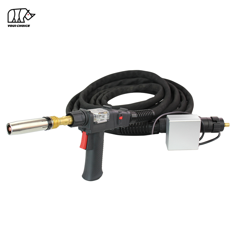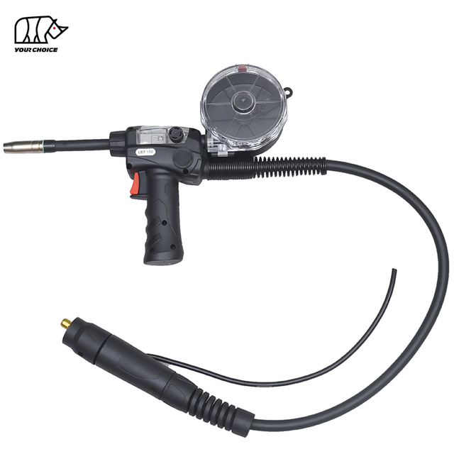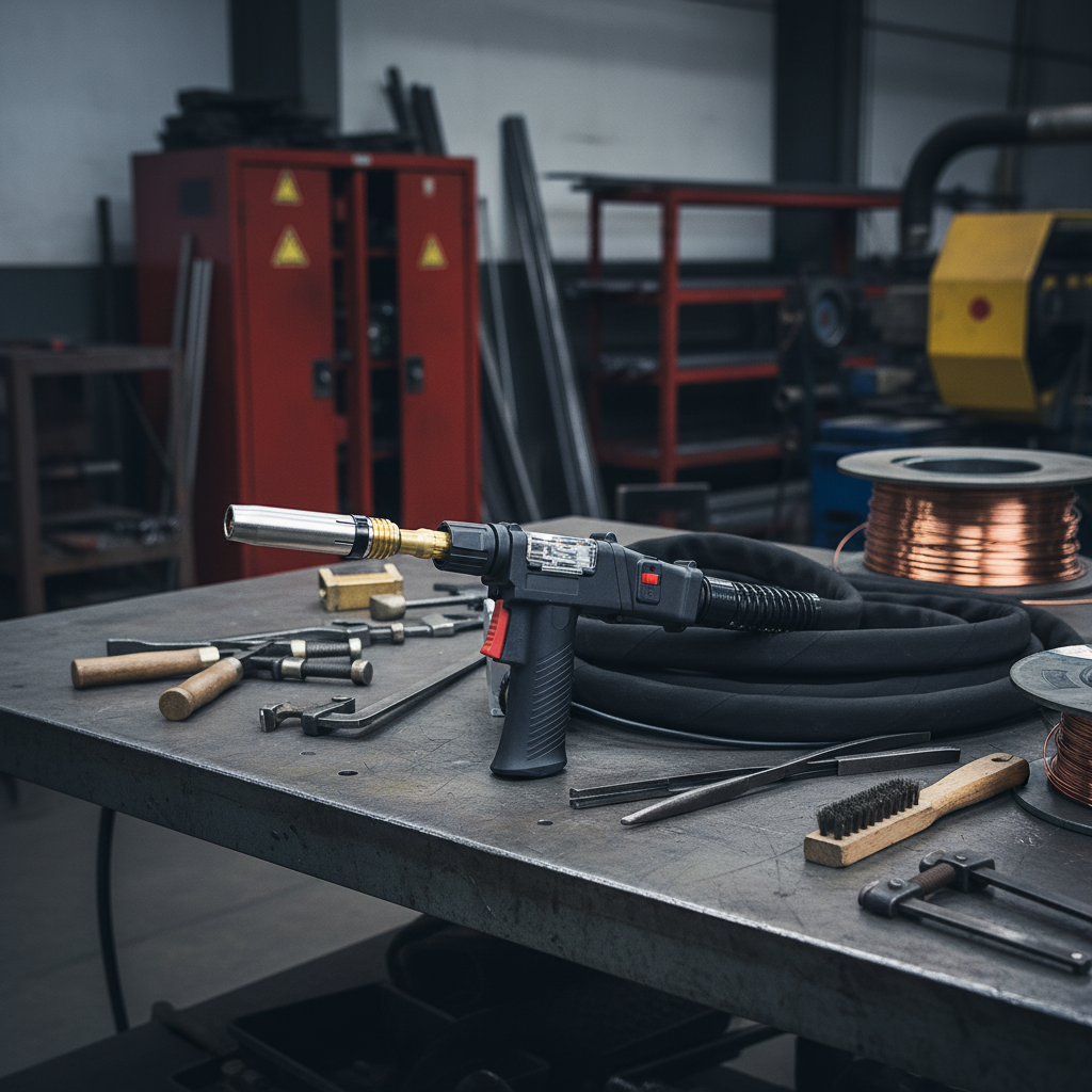
LPA300 Push-Pull MIG Welding Gun Overview
The INWELT LPA300 Gas-Cooled Push-Pull MIG Welding Gun is designed for aluminum MIG welding applications that require coordinated wire feeding and an extended working reach.
Unlike a conventional push-only MIG gun, a push-pull welding system uses the wire feeder to push the welding wire while a motor in the gun helps pull it through the cable assembly. This coordinated feeding arrangement is particularly useful for softer aluminum welding wires, which can be more difficult to feed through long gun cables.
The INWELT LPA300 supports Ø1.2–1.6 mm welding wire and is available with 6 m, 8 m, 10 m and 12 m cable assemblies.
The product is listed with a rated current of 300A using CO₂ and 270A using mixed shielding gas at a 60% duty cycle. For aluminum welding with argon shielding gas, the applicable current rating should be confirmed for the specific operating conditions.
INWELT supplies LPA300 push-pull welding guns for industrial fabrication, welding equipment distributors, OEM projects and bulk purchasing requirements.
LPA300 Push-Pull Welding Gun Technical Specifications
| Specification | INWELT LPA300 |
| Product Model | LPA300 |
| Product Type | Push-Pull MIG Welding Gun |
| Welding Process | MIG / GMAW |
| Primary Application | Aluminum MIG Welding |
| Cooling Method | Gas Cooled / Air Cooled |
| Rated Current with CO₂ | 300A |
| Rated Current with Mixed Gas | 270A |
| Duty Cycle | 60% |
| Welding Wire Diameter | Ø1.2–1.6 mm |
| Standard Cable Length | 6 / 8 / 10 / 12 m |
| Torch Head | Angled torch head configuration |
| Listed Connection | Euro Central Connector |
| Wire Feed System | Push-Pull |
| Wire Feed Control | Torch-mounted speed adjustment listed |
| Brand | INWELT |
| Customization | Logo, Packaging, Cable Length, OEM/ODM |
The current ratings above correspond to the conditions listed for the INWELT LPA300. They should not be interpreted as an independently verified pure-argon current rating.
Before ordering, confirm the welding power source, wire feeder, motor-control interface, cable assembly and consumable configuration.
How Does a Push-Pull MIG Welding Gun Work?
A push-pull MIG welding gun uses two coordinated wire-feeding actions to move the electrode wire from the supply spool to the welding arc.
The primary feeder pushes welding wire into the torch cable, while the gun-mounted drive mechanism pulls the wire toward the contact tip.
By coordinating these feeding forces, a push-pull system can reduce wire compression and feeding instability inside a long cable assembly.
Feeder-Side Push Motor and Gun-Side Pull Motor
The feeder-side drive system supplies welding wire from the main wire spool.
The gun-side drive system provides additional pulling force near the welding arc.
For stable operation, both systems must be correctly configured.
Important setup factors include:
Incorrect motor coordination or excessive pressure can damage soft welding wire and cause feeding problems.
Why Push-Pull Feeding Helps with Aluminum Wire
Aluminum welding wire is generally softer and more susceptible to deformation than common solid steel MIG welding wire.
When aluminum wire is pushed through a long cable, excessive resistance can contribute to wire buckling, feeding interruptions and birdnesting.
A properly configured push-pull system helps support the wire as it travels through the torch cable.
This makes push-pull feeding useful for industrial aluminum MIG welding applications requiring longer cable assemblies.
However, the push-pull mechanism does not eliminate the need for correct drive rolls, liners, contact tips and feeding adjustments.

Key Features of the INWELT LPA300
300A CO₂ and 270A Mixed-Gas Ratings
The LPA300 is listed with the following current ratings:
These values describe the manufacturer's published configurations.
For aluminum MIG welding, pure argon is commonly used as the shielding gas, while specific applications may use other suitable argon-based mixtures.
Buyers should confirm the LPA300 current rating under the intended aluminum welding conditions before selecting the torch for continuous production.
Air-Cooled Design and 60% Duty Cycle
The LPA300 uses an air-cooled torch configuration.
It does not require a separate liquid-cooling circuit.
The 60% duty cycle must be considered when evaluating the thermal requirements of the welding process.
At the specified rated conditions, a 60% duty cycle corresponds to six minutes of welding within a standard ten-minute operating period.
For applications with extended arc-on time or higher thermal loads, the actual torch operating limits should be evaluated before installation.
6 m, 8 m, 10 m and 12 m Cable Options
INWELT offers four listed cable lengths:
| Cable Length | Typical Selection Consideration |
| 6 m | Compact industrial welding stations |
| 8 m | Fabrication benches and general industrial work areas |
| 10 m | Larger workpieces and extended working reach |
| 12 m | Welding stations requiring greater movement from the feeder |
Longer cable assemblies provide additional working reach, but they also make wire-feed system selection and installation more important.
The cable should be routed to avoid sharp bends, twisting and mechanical damage.
The appropriate cable length depends on the production layout, equipment configuration and welding application.
Torch-Mounted Wire Feed Speed Control
The LPA300 product description lists a torch-mounted wire feed speed adjustment feature.
This provides an operating interface for adjusting the wire-feed setting in compatible system configurations.
However, the electrical control function must match the connected power source and wire feeder.
For OEM and replacement projects, confirm:
Wire feed speed control signal
Motor supply voltage
Motor current requirements
Control connector pinout
Trigger wiring
Feeder coordination requirements
A matching mechanical connector alone does not guarantee that the gun-mounted motor or speed control will function correctly.
Angled Torch Head Configuration
The LPA300 uses an angled torch head configuration for manual MIG welding.
Torch neck geometry affects access to the joint, welding position and the relationship between the contact tip and workpiece.
For replacement applications, verify the front-end consumable dimensions and torch head configuration.
Any interchangeability with other torch head systems should be confirmed through actual part references or technical drawings.
LPA300 Aluminum Welding Wire and Consumable Selection
The LPA300 is specified for welding wire diameters from Ø1.2 mm to Ø1.6 mm.
The contact tip, wire liner and drive rolls must be selected according to the actual aluminum wire diameter and alloy.
Supported Welding Wire Diameters
| Wire Diameter | Selection Requirement |
| Ø1.2 mm | Match contact tip, liner and drive rolls |
| Ø1.4 mm | Confirm the corresponding consumable configuration |
| Ø1.6 mm | Confirm contact tip, liner, drive rolls and feeding capacity |
Aluminum Welding Wire Types
Common aluminum MIG filler wires include ER4043 and ER5356.
The appropriate filler metal depends on the base material, welding procedure, mechanical requirements and applicable welding standards.
The availability of an LPA300 feeding configuration for each wire alloy should be verified before ordering.
Contact Tip Selection
The contact tip transfers welding current to the electrode wire.
For aluminum welding, contact-tip sizing requires attention to wire diameter and the thermal expansion characteristics of the filler wire.
The correct bore and thread dimensions should be confirmed using the selected consumable specification.
An incorrect contact tip may contribute to feeding resistance, inconsistent current transfer or burnback.
Wire Liner Selection
The liner guides welding wire through the cable assembly.
For aluminum welding, liner material, internal diameter, length and installation condition can all affect wire feeding.
The correct liner should be selected according to:
Aluminum wire diameter
Wire alloy
Cable length
Torch configuration
Feeder requirements
Avoid installing an unspecified steel-wire liner configuration without checking its suitability for aluminum wire.
Drive Roll Selection
Drive rolls must provide sufficient traction without excessively deforming the soft aluminum wire.
U-groove drive rolls are commonly used for aluminum MIG wire-feeding applications.
The exact groove size, roll dimensions and required pressure should be matched to the wire and gun-mounted drive system.

LPA300 Welding Machine and Wire Feeder Compatibility
The LPA300 is listed with a Euro Central Connector configuration.
However, a push-pull MIG gun requires more than a compatible welding power connector.
The gun-side drive motor must receive the correct electrical supply and control signals, and it must operate in coordination with the main wire feeder.
Euro Connector and Motor-Control Requirements
A compatible installation may require the following connections:
| System Component | Compatibility Requirement |
| Welding Power | Correct current-carrying connection |
| Shielding Gas | Compatible gas connection and flow path |
| Welding Wire | Correct wire-feed inlet and liner configuration |
| Trigger | Matching control circuit |
| Gun-Side Pull Motor | Correct supply voltage and current |
| Wire Feed Speed Control | Compatible control signal |
| Feeder Control | Coordinated push and pull motor operation |
| Cable Assembly | Appropriate length and connector arrangement |
A standard Euro connector can provide mechanical, welding-power, gas and trigger connections in certain systems, but it does not automatically provide every control function needed by a motorized push-pull gun.
An additional control connection or compatible feeder interface may be required.
Compatibility Checklist Before Ordering
Before purchasing the INWELT LPA300, provide:
Welding machine manufacturer and model
Wire feeder manufacturer and model
Existing welding gun type
Main connector photographs
Motor-control connector type
Motor supply and control specifications
Required wire diameter and alloy
Selected cable length
Required contact tip and liner configuration
Order quantity
For replacement projects, a wiring diagram or existing gun sample is especially useful.
INWELT can review the required interface configuration before quotation.

Push-Pull MIG Gun vs. Spool Gun vs. Standard MIG Gun
Although all three gun types can be used for MIG welding, their wire-feed arrangements are different.
| Feature | Push-Pull MIG Gun | Spool Gun | Standard MIG Gun |
| Wire Spool Location | Main feeder | On the gun | Main feeder |
| Gun-Side Drive Motor | Yes | Yes | Usually no |
| Main Feeder Push Drive | Yes | Not used in the same way | Yes |
| Long-Cable Aluminum Feeding | A key application | Wire feeds locally from gun spool | More dependent on setup |
| Gun Weight Consideration | No large wire spool on gun | Includes small wire spool | Typically simpler gun assembly |
| Key Compatibility Check | Feeder and motor control | Spool gun control interface | Standard torch connection |
When Should You Choose a Push-Pull MIG Gun?
Consider a push-pull system when:
Aluminum wire must be fed through an extended cable assembly
The application uses a remote wire spool
Industrial production requires a coordinated wire-feeding system
The welding power source and feeder support push-pull operation
When Is a Spool Gun More Suitable?
A spool gun may be more suitable when a local wire spool at the gun is acceptable and the equipment supports that spool gun configuration.
Spool guns and push-pull guns should not be treated as interchangeable products.
How to Set Up a Push-Pull MIG Welding Gun
Correct setup is essential for reliable operation.
Step 1: Confirm Equipment Compatibility
Verify that the welding power source and wire feeder can support the motorized push-pull gun.
Check the electrical interface, motor supply and control requirements.
Step 2: Install the Correct Wire Feeding Components
Select the contact tip, liner and drive rolls according to the welding wire diameter and alloy.
Inspect the wire path before installation.
Step 3: Connect the Welding Gun
Connect the welding-power, shielding-gas, trigger and push-pull control interfaces according to the approved equipment configuration.
Do not connect an unidentified motor-control plug without verifying its electrical requirements.
Step 4: Set Drive Roll Pressure
Use the appropriate drive-roll pressure for the selected aluminum wire.
Excessive pressure can deform soft welding wire, while insufficient pressure can cause slippage.
Step 5: Coordinate Push and Pull Feeding
Configure the main feeder and gun-mounted pull motor according to the compatible control system.
The aim is to feed wire without excessive tension, compression or slippage.
Step 6: Check Cable Routing
Lay out the cable with smooth bends and avoid unnecessary twisting.
Inspect the full cable length before starting production.
Step 7: Perform a Controlled Welding Test
Carry out initial setup and verification in accordance with the welding machine and feeder instructions.
Check wire feeding, trigger operation, shielding gas and arc stability.
Only begin production after the system has been verified for the intended application.
Common Push-Pull MIG Gun Problems and Solutions
Push-pull welding guns require correct electrical coordination and consumable selection.
| Problem | Possible Cause | Recommended Check |
| Wire birdnesting | Excessive pushing force or poor motor coordination | Check feeder settings and pull motor operation |
| Wire slipping | Incorrect drive-roll pressure or groove | Check rolls, wire diameter and pressure |
| Irregular wire feeding | Damaged liner or cable bends | Inspect liner and cable routing |
| Pull motor not running | Control wiring or motor supply problem | Verify motor interface and feeder compatibility |
| Wire feeding too fast or slow | Incorrect speed control setting | Check control configuration |
| Contact tip burnback | Feeding interruption or incorrect tip | Inspect wire feed, tip and welding parameters |
| Torch overheating | Current or duty cycle exceeded | Check thermal rating and electrical connections |
| Poor shielding-gas coverage | Gas leak or blocked nozzle | Inspect gas supply and nozzle |
| Unstable arc | Inconsistent feeding or electrical contact | Inspect feeding system and current connections |
Why Does a Push-Pull MIG Gun Cause Birdnesting?
Birdnesting can occur if the main feeder pushes wire faster than the gun-side system can accommodate it, or if there is excessive resistance in the wire path.
Check the feeder coordination, drive rolls, liner and cable routing.
Why Is Aluminum Wire Slipping in the Drive Rolls?
Wire slipping may result from insufficient drive-roll pressure, an incorrect groove size or contaminated drive components.
Use the correct drive-roll specification and adjust pressure according to the wire and feeding equipment.
Why Is the Push-Pull Gun Motor Not Running?
Possible causes include an incompatible control connector, incorrect motor supply, damaged wiring or a feeder that does not support the required push-pull control system.
Electrical faults should be diagnosed by qualified personnel using the applicable equipment documentation.
Maintenance and Replacement Parts for LPA300
Routine inspection can help maintain the wire-feeding and welding functions of the LPA300.
Inspect the Gun-Side Drive Mechanism
Check the drive rolls and wire path for wear, contamination or incorrect adjustment.
Follow the manufacturer's maintenance instructions for the motor and drive mechanism.
Check Contact Tips and Gas Nozzles
Inspect contact tips for bore wear and gas nozzles for excessive spatter or deformation.
Replace damaged components with parts that match the LPA300 torch configuration.
Inspect the Wire Liner
Check the liner when feeding resistance increases or wire movement becomes inconsistent.
Confirm the correct liner diameter and length for the installed cable assembly.
Inspect the Cable and Control Wiring
Inspect the power cable, control wiring and connectors for visible damage.
Long cable assemblies should be checked for abrasion, twisting and excessive bending.
Verify Speed Control Operation
If equipped with torch-mounted speed adjustment, verify that the control operates correctly with the matched feeder system.
Disconnect the welding equipment before servicing the gun, and follow the equipment manufacturer's electrical safety procedures.
Replacement Parts to Confirm Before Bulk Orders
| Replacement Component | Information Required |
| Contact Tip | Wire diameter, bore, thread and length |
| Gas Nozzle | Front-end configuration and dimensions |
| Gas Diffuser | Torch head compatibility |
| Wire Liner | Wire type, size and cable length |
| Drive Rolls | Groove type, diameter and mounting dimensions |
| Pull Motor | Electrical rating and mechanical configuration |
| Trigger Switch | Switch and wiring arrangement |
| Speed Control | Control type and electrical interface |
| Torch Head | Neck dimensions and attachment |
| Cable Assembly | Length, connectors and control wiring |
Provide a sample, part number or technical drawing for precise replacement-part matching.
Industrial Applications of the LPA300 Aluminum MIG Gun
The LPA300 is intended for aluminum MIG welding applications where its wire-feeding, thermal and equipment compatibility requirements are satisfied.
Aluminum Structural Fabrication
Push-pull wire feeding can support the fabrication of aluminum frames, profiles and structural assemblies.
Actual suitability depends on the welding procedure, material thickness and operating requirements.
Trailer and Vehicle Manufacturing
Aluminum components used in trailers and commercial vehicle fabrication may require extended torch reach and controlled wire feeding.
The welding system should be selected according to the joint design, filler metal and production conditions.
Aluminum Equipment Enclosures
Manufacturers of aluminum housings, covers, cabinets and other fabricated components may benefit from a push-pull setup where extended cable lengths are required.
Industrial Aluminum Assembly
Push-pull MIG welding systems are used in manufacturing environments that require reliable feeding of suitable aluminum filler wires.
Maintenance and Repair
The LPA300 can be evaluated for industrial maintenance and repair work where the existing welding equipment supports the required push-pull control system.
LPA300 Push-Pull Welding Guns for OEM and Wholesale Buyers
INWELT supplies push-pull MIG welding guns for welding equipment distributors, OEM customers, industrial suppliers and bulk purchasing projects.
Standard LPA300 Supply Options
Available listed configurations include:
All required electrical interfaces and replacement components should be confirmed before ordering.
OEM and Private-Label Push-Pull MIG Guns
INWELT can review OEM/ODM requirements for:
Customization feasibility depends on the technical requirements and approved product configuration.
Push-Pull MIG Guns for Welding Equipment Distributors
For distributors, a complete purchasing specification should include the gun model, equipment compatibility, wire sizes, cable length and replacement components.
This helps support inventory management, repeat ordering and after-sales service.
For OEM projects, INWELT recommends reviewing connection drawings and sample requirements before volume production.
Frequently Asked Questions About Push-Pull MIG Guns
What is a push-pull MIG welding gun?
A push-pull MIG welding gun uses a feeder-side motor to push welding wire and a gun-side motor to pull the wire. The coordinated system helps feed suitable welding wire through longer cables.
What is the INWELT LPA300?
The INWELT LPA300 is a gas-cooled push-pull MIG welding gun designed for aluminum welding applications. It supports Ø1.2–1.6 mm wire and is available with 6 m, 8 m, 10 m and 12 m cable assemblies.
What is the current rating of the LPA300?
The published LPA300 specifications list 300A with CO₂ and 270A with mixed gas at a 60% duty cycle. The appropriate rating for aluminum welding with pure argon must be confirmed separately.
Is the LPA300 air-cooled or water-cooled?
The LPA300 is a gas-cooled, also called air-cooled, push-pull MIG welding gun.
Can a push-pull MIG gun weld aluminum?
Yes. Push-pull MIG systems are commonly used to feed softer aluminum welding wires through extended torch cables. Correct system setup and equipment compatibility are essential.
What aluminum wire sizes does the LPA300 support?
The LPA300 is specified for Ø1.2–1.6 mm welding wire. The contact tip, liner and drive rolls must match the selected wire diameter and alloy.
What cable lengths are available?
INWELT lists 6 m, 8 m, 10 m and 12 m cable options for the LPA300.
What is the difference between a push-pull MIG gun and a spool gun?
A push-pull gun uses coordinated feeder-side and gun-side drive motors, with the wire spool usually located at the main feeder. A spool gun carries a small wire spool directly on the gun.
Can the LPA300 connect to any MIG welder with a Euro connector?
No. Mechanical connector compatibility alone is insufficient. The welding machine and feeder must also support the required motor supply, speed control and coordinated push-pull operation.
Does the LPA300 have wire feed speed control?
The INWELT product description lists torch-mounted wire feed speed adjustment. Compatibility of this function must be verified with the selected feeder and electrical control system.
Can I use ER4043 or ER5356 aluminum wire?
These are common aluminum MIG filler wires. The correct drive rolls, liner, contact tip and feeding configuration should be confirmed for the selected alloy and diameter.
Does a push-pull welding gun prevent all wire feeding problems?
No. A correctly configured push-pull system helps manage soft-wire feeding, but wire jams and other problems can still occur because of incorrect drive pressure, damaged liners, poor motor coordination or unsuitable components.
What should I check before ordering a replacement push-pull MIG gun?
Check the welding machine, wire feeder, power connector, motor-control wiring, wire diameter, cable length, drive system and consumable specifications.
Does INWELT supply OEM push-pull MIG welding guns?
INWELT supports OEM/ODM inquiries involving cable lengths, connector specifications, product labeling, packaging and other project requirements.
Can distributors order the LPA300 in bulk?
Yes. INWELT provides LPA300 push-pull MIG welding guns for wholesale, distributor and industrial procurement inquiries.
Request an LPA300 Push-Pull MIG Welding Gun Quote
Looking for a push-pull MIG welding gun manufacturer for aluminum welding applications?
INWELT supplies LPA300 gas-cooled push-pull MIG welding guns for distributors, importers, OEM brands and industrial buyers.
For an accurate quotation, please provide:
Model: LPA300
Welding machine manufacturer and model
Wire feeder manufacturer and model
Required welding wire diameter and alloy
Cable length: 6 / 8 / 10 / 12 m
Connector and motor-control requirements
Existing welding gun or sample details
Required consumables and spare parts
Estimated order quantity
OEM/ODM requirements
Destination market
Contact INWELT for LPA300 Push-Pull MIG Welding Gun Specifications, Compatibility Review, Bulk Pricing and OEM/ODM Supply.
 English
 简体中文
 العربية
 Français
 Русский
 Español
 Português
 Deutsch
 italiano
 日本語
 한국어
 Nederlands
 Tiếng Việt
 ไทย
 Polski
 Türkçe
 ភាសាខ្មែរ
 Bahasa Melayu
 Filipino
 Bahasa Indonesia
 magyar
 Română
 Čeština
 Монгол
 қазақ
 Српски
 हिन्दी
 فارسی
 Slovenčina
 Slovenščina
 Norsk
 Svenska
 українська
 Ελληνικά
 Suomi
 Latine
 Dansk
 বাংলা
 Hrvatski
 Afrikaans
 Gaeilge
 Eesti keel
 नेपाली
 Oʻzbekcha
 latviešu
 Azərbaycan dili
 Беларуская мова
 Bosanski
 Български
 ქართული
 Lietuvių