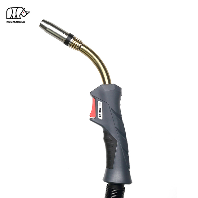
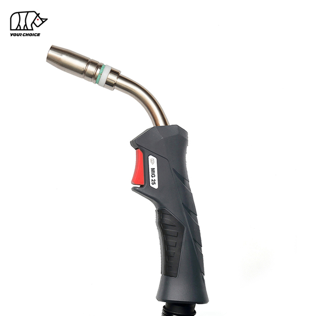
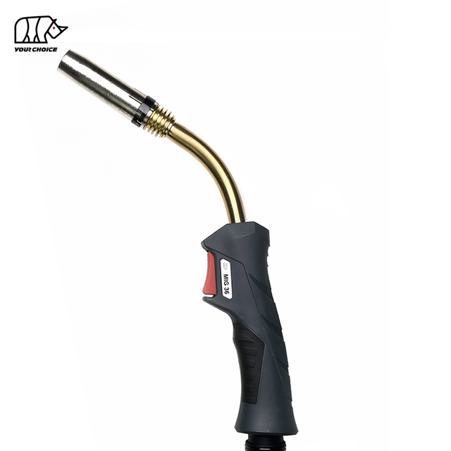
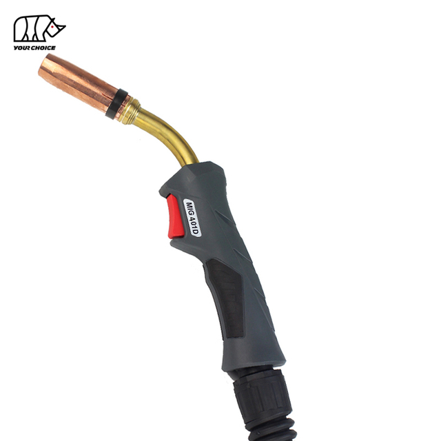
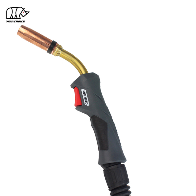
You are here:Home » News » Welding Technology » Why Does the Welding Torch Produce Spatter in High-Precision Welding? A Costly but Often Overlooked Torch Selection Mistake
Why Does the Welding Torch Produce Spatter in High-Precision Welding? A Costly but Often Overlooked Torch Selection Mistake
Views: 0 Author: Site Editor Publish Time: 2026-09-02 Origin: Site
Excessive spatter in high-precision welding is not always caused by incorrect voltage or wire feed speed. An incorrectly selected welding torch can create unstable electrical contact, inconsistent wire feeding, inadequate shielding gas delivery, excessive heat buildup, and variations in contact-tip-to-work distance, all of which can destabilize metal transfer and increase spatter.
This problem is particularly important in precision MIG/MAG and Gas Metal Arc Welding (GMAW), where repeatable wire delivery and stable electrical transfer are essential.
A welding machine may have perfectly optimized parameters, but if the torch, contact tip, liner, cable assembly, cooling method, or duty cycle does not match the application, the arc may still behave inconsistently.
The result is often blamed on the welding machine.
In reality, the root cause may be a much simpler—and more expensive—selection mistake:
The welding torch was selected by amperage alone instead of being selected as part of the complete welding system.
For high-precision manufacturing, this mistake can lead to more than visible spatter. It can increase consumable consumption, cleaning labor, rework, production interruptions, rejected components, and total cost per welded part.
Why Can the Wrong Welding Torch Cause Excessive Spatter?
The wrong welding torch can increase spatter because the torch controls three critical elements at the arc: welding current, filler-wire delivery, and shielding gas. If the contact tip, liner, cooling capacity, cable length, nozzle geometry, or duty cycle is unsuitable, the arc becomes less stable and molten metal transfer becomes less consistent.
Torch-Related Problem
Effect on Welding
Possible Result
Incorrect contact tip size
Poor electrical contact or excessive wire friction
Unstable arc and spatter
Worn contact tip
Wire movement inside tip
Arc wandering and spatter
Incorrect liner
Inconsistent wire feeding
Arc fluctuations
Excessive wire-feed resistance
Irregular wire speed
Unstable metal transfer
Insufficient torch rating
Excessive heat buildup
Contact instability
Low duty-cycle capacity
Torch overheats during production
Consumable wear and downtime
Poor gas distribution
Unstable shielding environment
Spatter and weld defects
Incorrect torch neck geometry
Inconsistent CTWD or angle
Variable penetration and arc behavior
Excessive cable length or poor routing
Higher wire-feed resistance
Feeding instability
Wrong cooling method
Thermal instability
Shorter consumable life
Key takeaway: In precision welding, the welding torch is not simply a handle that holds the contact tip. It is a current-transfer, wire-delivery, gas-delivery, and thermal-management system.
What Does “Torch-Selection-Induced Spatter” Mean?
Torch-selection-induced spatter is excessive molten-metal ejection caused or amplified by a welding torch configuration that does not properly support the required current, wire diameter, duty cycle, wire-feed stability, shielding gas flow, or welding geometry.
This differs from purely parameter-induced spatter.
Traditional troubleshooting often starts with:
voltage → wire feed speed → shielding gas → welding speed.
Those parameters are important.
However, high-precision applications should also examine:
In GMAW, welding wire must travel continuously from the wire feeder through the cable and liner, pass through the contact tip, receive electrical current, exit the torch at a controlled position, and enter the arc at a repeatable speed.
Any instability along this path can become arc instability.
And arc instability frequently becomes spatter.
Why Does Contact Tip Selection Have Such a Large Effect on Spatter?
The contact tip performs one of the most important functions inside a MIG/MAG welding torch:
it transfers welding current from the torch to the moving welding wire.
For high-precision welding, that electrical connection must remain highly consistent.
What Happens If the Contact Tip Is Too Large?
If the contact-tip bore is excessively large relative to the wire diameter, the wire has more freedom to move inside the tip.
This can result in:
inconsistent electrical contact;
wire wandering;
changing arc position;
unstable current transfer;
inconsistent contact-tip-to-work distance;
premature wear.
The arc may repeatedly shift rather than remaining concentrated at a stable point.
In conventional fabrication, small variations may be tolerated.
In precision welding, the same variation can cause visible differences in spatter, bead position, penetration, and weld appearance.
What Happens If the Contact Tip Is Too Small?
A contact tip that is too tight can create excessive friction.
That can produce:
wire-feed resistance;
irregular wire speed;
wire hesitation;
burnback;
premature tip wear;
feeding interruptions.
When wire delivery becomes inconsistent, the relationship between wire feed speed and arc voltage changes continuously.
The resulting metal transfer may become irregular, increasing the probability of spatter.
Therefore:
The correct contact tip must match both the wire diameter and the actual welding application—not simply fit inside the torch.
Why Does a Worn Contact Tip Increase Welding Spatter?
A contact tip gradually wears as welding wire continuously passes through it.
As the bore becomes enlarged, electrical contact becomes less repeatable.
This can cause the wire to change its contact point inside the tip from moment to moment.
In a high-precision welding process, that variation matters.
The operator or automated system may maintain exactly the same:
voltage;
amperage;
travel speed;
torch angle;
wire feed speed.
But the electrical transfer point inside the torch is no longer consistent.
The result may be:
stable machine settings + unstable physical current transfer = unstable arc behavior.
This is why replacing a contact tip should not be based only on whether the tip is completely unusable.
For precision production, the more relevant question is:
Has the contact tip worn enough to affect process repeatability?
How Does the Torch Liner Affect Welding Spatter?
The liner guides welding wire from the feeder through the welding torch cable. Incorrect liner size, excessive friction, contamination, poor installation, or excessive cable bending can create irregular wire feeding and therefore unstable metal transfer.
Wire feeding should be smooth and continuous.
When the wire encounters resistance, its instantaneous feed rate at the contact tip may not perfectly match the commanded wire-feed speed.
In a normal workshop, the welder may simply hear the arc sound changing.
In a precision production line, this small instability can appear as:
increased micro-spatter;
inconsistent bead profile;
variable penetration;
arc wandering;
contact-tip wear;
burnback.
Can a Liner Be Technically “Compatible” but Still Be Wrong?
Yes.
A liner may physically fit the torch but still be unsuitable for the application.
Liner selection should consider:
Selection Factor
Why It Matters
Wire diameter
Determines required internal clearance
Wire material
Different wires have different stiffness and friction
Torch cable length
Longer feeding paths increase resistance
Cable bends
Tight bends increase friction
Wire-feed speed
High-speed feeding demands greater consistency
Welding mode
Precision and pulsed processes are less tolerant of feeding variation
Production duty cycle
Continuous production accelerates wear
Liner condition
Dirt and debris increase drag
This is one reason replacing only the contact tip may not solve repeated spatter problems.
The entire wire path should be evaluated.
Is Choosing a Welding Torch by Maximum Amperage a Mistake?
Yes. Selecting a welding torch only by its advertised maximum amperage is one of the most common selection mistakes in demanding welding applications.
Two torches can have similar amperage ratings and still perform very differently in actual production.
A high-precision torch should be selected according to:
Requirement
What Should Be Evaluated?
Welding current
Actual continuous current
Duty cycle
Real arc-on time
Wire diameter
Contact tip and liner compatibility
Wire material
Feeding characteristics
Welding mode
Short-circuit, spray, pulsed or other transfer
Cooling
Gas/air or water cooling
Cable length
Feed resistance and operator reach
Torch neck
Access and CTWD consistency
Nozzle
Gas coverage and joint accessibility
Production method
Manual, robotic or automated
Consumable life
Stability over production time
Maintenance
Replacement frequency and accessibility
A torch rated for the required amperage may still be unsuitable if the production duty cycle is much higher than the torch was designed to support.
This is where the apparent “cheaper torch” can become the expensive choice.
Why Is Duty Cycle Critical in High-Precision Welding?
Duty cycle determines how much continuous thermal loading a welding torch can tolerate at a specified operating condition.
Precision welding requires more than simply avoiding catastrophic overheating.
The process needs thermal consistency.
As the torch temperature rises, several components may experience accelerated wear:
contact tips;
nozzles;
diffusers;
liners;
insulating components;
cable assemblies.
Even before a torch becomes too hot to use, increasing temperature can influence the condition of the consumables.
That matters because precision welding depends on repeatability.
A process that produces excellent welds during the first 10 minutes but increasing spatter after prolonged production is not truly stable.
Why Is Welding Torch Cooling a Precision Issue, Not Just an Operator Comfort Issue?
Cooling is often viewed as a comfort feature.
For precision welding, it is better understood as a process-stability feature.
A properly cooled torch helps maintain a more consistent thermal environment around:
the contact tip;
diffuser;
nozzle;
torch neck;
power cable.
When thermal load exceeds the torch's effective cooling capacity, consumable wear may accelerate.
This can eventually change the geometry or electrical characteristics around the arc.
When Should Water Cooling Be Considered?
There is no universal amperage at which every application must change from an air/gas-cooled torch to a water-cooled torch.
The decision should consider:
current + duty cycle + weld duration + torch size + access requirements + production volume.
Water cooling becomes increasingly attractive when:
welding current is high;
production is continuous;
arc-on time is long;
torch dimensions must remain compact;
consumable temperature is difficult to control;
production requires high repeatability.
The correct cooling system should therefore be selected according to the real production cycle rather than peak current alone.
How Does Shielding Gas Delivery Through the Torch Affect Spatter?
A welding torch is also responsible for delivering shielding gas to the weld zone.
The shielding gas path includes several components:
gas hose → torch body → diffuser → nozzle → weld zone.
Problems anywhere in this path may disturb gas coverage.
Possible causes include:
damaged gas hoses;
blocked diffuser holes;
excessive spatter inside the nozzle;
unsuitable nozzle dimensions;
leaks;
incorrect nozzle position;
turbulent gas flow.
Poor shielding primarily increases the risk of weld contamination and porosity, but an unstable arc environment can also contribute to poor overall transfer behavior.
For high-precision welding, gas flow should therefore be evaluated not only at the regulator.
The important question is:
Is the gas reaching the arc consistently and uniformly?
Can Torch Neck Geometry Cause More Spatter?
Yes—indirectly.
Torch-neck geometry determines how easily the operator or automated system can maintain the required:
work angle;
travel angle;
CTWD;
arc position;
joint access.
If the torch geometry is poorly matched to the joint, the operator may compensate by changing the torch angle or increasing stickout.
That can change arc behavior.
In high-precision applications, small deviations that would be acceptable in general fabrication may become important.
Therefore, the “best” welding torch is not necessarily the torch with the highest amperage.
It is the torch that allows the required welding geometry to be reproduced consistently.
What Is CTWD and Why Does It Matter for Spatter?
Contact Tip to Work Distance (CTWD) is the distance from the end of the contact tip to the workpiece. In GMAW, variations in CTWD affect electrical stickout, welding current, arc behavior, deposition characteristics, and process stability.
For precision welding, CTWD should be highly repeatable.
If the torch design or operator access makes CTWD difficult to maintain, welding conditions can vary even when the machine settings remain unchanged.
Typical causes of inconsistent CTWD include:
unsuitable torch-neck angle;
excessive nozzle length;
poor joint accessibility;
operator fatigue;
incorrect robotic torch positioning;
contact-tip position changes;
inconsistent consumable installation.
This is why torch ergonomics and geometry are not simply convenience features.
They affect process repeatability.
How Does Welding Cable Length Affect Arc and Wire-Feed Stability?
Longer torch assemblies provide greater working reach, but they also create a longer path for the welding wire.
The longer the feeding path, the more important liner condition, cable routing, wire stiffness, and feeder performance become.
Problems increase when long cables are:
tightly coiled;
repeatedly bent;
routed around machinery;
twisted during production;
combined with an incorrect liner.
For precision applications, selecting the longest possible cable “just in case” is not always the best strategy.
The preferred cable length is generally:
long enough for required movement, but no longer than necessary.
This helps reduce unnecessary wire-feed resistance.
Why Does Torch Selection Matter More in Pulsed and Precision Welding?
High-precision welding processes are designed to control heat input, droplet transfer and arc behavior more accurately.
That makes process consistency more valuable—and mechanical instability more visible.
A sophisticated welding power source cannot fully compensate for:
inconsistent wire feeding;
worn contact tips;
unstable current transfer;
poor gas delivery;
excessive torch temperature;
changing CTWD.
This leads to an important principle:
The more precise the welding process becomes, the more important torch-system consistency becomes.
Investing heavily in the power source while treating the welding torch as a generic accessory can therefore undermine the precision the equipment was purchased to provide.
Why Is Torch Selection Even More Important in Robotic Welding?
However, that means torch-related variations become even easier to identify.
A robotic system expects the torch to repeatedly return to the same:
tool center point;
angle;
CTWD;
wire position;
gas coverage.
Consumable wear or thermal distortion can compromise that repeatability.
For robotic and automated welding, evaluate:
Factor
Precision Requirement
Torch neck
High dimensional repeatability
Contact tip
Consistent bore and electrical transfer
Tip installation
Repeatable position
Liner
Low wire-feed resistance
Cable routing
Stable robot movement
Cooling
Consistent thermal performance
Nozzle
Stable gas coverage
Consumable life
Predictable maintenance intervals
A torch that performs acceptably in manual welding may not automatically provide the repeatability required by automation.
How Much Does Welding Spatter Really Cost?
The visible metal droplets are only part of the cost.
The real cost of spatter can be expressed as:
Total Spatter Cost = Cleanup Labor + Consumables + Rework + Downtime + Rejected Parts + Downstream Process Problems
1. Cleanup Labor
Spatter may need to be removed before:
painting;
coating;
plating;
sealing;
assembly;
final inspection.
2. Higher Consumable Consumption
Heavy spatter can increase cleaning and replacement frequency for:
nozzles;
contact tips;
diffusers.
3. Production Downtime
Every time the operator stops to clean a nozzle or replace a contact tip, arc-on productivity decreases.
4. Rework
Arc instability may affect more than spatter.
It can also create inconsistent bead geometry or penetration, requiring additional inspection and repair.
5. Downstream Quality Problems
For precision components, even small amounts of spatter can interfere with:
sealing surfaces;
threads;
moving components;
coating quality;
cosmetic appearance.
Therefore, the cheapest torch at the purchasing stage may not deliver the lowest cost per welded component.
Is the Welding Torch Really Causing the Spatter?
Not always.
Spatter can also be caused by welding parameters, material contamination, shielding gas, wire quality, grounding, welding technique, and metal-transfer mode.
The best troubleshooting method is to identify the variable systematically.
Symptom
Possible Torch-Related Cause
Also Check
Spatter increases gradually
Contact-tip wear or torch heating
Parameters
Arc wanders
Worn/oversized contact tip
Ground connection
Wire hesitates
Liner or cable resistance
Feeder
Burnback occurs
Tip/liner/feed problem
Wire-feed setting
Spatter increases after cable bending
Wire-feed restriction
Cable routing
Spatter changes with torch position
Gas delivery or CTWD
Torch angle
Nozzle overheats
Insufficient cooling
Duty cycle
Stable at start, unstable later
Thermal overload
Consumable condition
Frequent tip replacement required
Wrong tip or torch capacity
Wire condition
Same parameters behave differently between torches
Torch-system variation
Consumable installation
The goal is to avoid changing welding parameters continuously when the underlying problem is mechanical.
How Should You Troubleshoot Welding Torch Spatter Step by Step?
Step 1: Verify the Welding Parameters
Confirm that voltage, wire feed speed, polarity, travel speed, and transfer mode are appropriate.
If the parameters are correct, continue troubleshooting rather than immediately adjusting them again.
Step 2: Inspect the Contact Tip
Check for:
excessive bore wear;
burnback;
deformation;
contamination;
incorrect size.
Step 3: Check Wire Feeding
Feed wire through the system and observe whether movement is smooth and consistent.
Inspect the liner and cable routing.
Step 4: Check the Torch Duty Cycle
Determine whether the torch is being used continuously near its thermal limit.
Step 5: Inspect Cooling Performance
Check whether the torch temperature increases significantly during production.
For water-cooled systems, confirm coolant circulation.
Step 6: Inspect Gas Delivery
Check the nozzle, diffuser, hoses, and gas path for restrictions or leaks.
Step 7: Verify CTWD and Torch Angle
Ensure the torch geometry allows the operator or robot to maintain repeatable positioning.
Step 8: Compare Performance with Production Time
Ask an important diagnostic question:
Does the spatter appear immediately, or does it increase after the torch has been welding for a period of time?
If performance deteriorates with temperature, torch capacity or cooling should receive greater attention.
How Should You Select a Welding Torch for High-Precision Welding?
A precision welding torch should be selected according to the complete application rather than a single specification.
Use the following selection framework:
Selection Parameter
Question to Ask
Welding process
What transfer mode will be used?
Current
What is the real operating amperage?
Duty cycle
How long is the arc actually on?
Wire
What material and diameter are used?
Contact tip
Is it optimized for the wire and current?
Liner
Is it suitable for the wire and cable length?
Cooling
Can it manage sustained thermal load?
Cable
What is the shortest practical length?
Torch neck
Can it maintain correct joint geometry?
Nozzle
Does it provide suitable gas coverage and access?
Automation
Is dimensional repeatability required?
Consumables
Are replacement intervals predictable?
Maintenance
Can components be serviced quickly?
This is a much stronger purchasing method than simply asking:
“How many amps is this welding torch?”
What Is the Most Common Welding Torch Selection Mistake?
The most expensive overlooked mistake is choosing a torch with enough nominal amperage but insufficient process stability for the actual production environment.
The torch may technically weld.
It may not fail immediately.
It may even appear acceptable during a short test.
But during real production it may experience:
excessive thermal buildup;
accelerating contact-tip wear;
increasing wire-feed resistance;
inconsistent arc behavior;
increasing spatter;
shorter consumable life;
more maintenance interruptions.
That is why short welding tests alone may not accurately represent production performance.
A high-precision welding torch should be evaluated under conditions that resemble the real:
current + wire + duty cycle + cable routing + joint geometry + production duration.
FAQ About Welding Torch Spatter in High-Precision Welding
Can the Wrong Welding Torch Really Cause Excessive Spatter?
Yes. A poorly matched welding torch can cause unstable wire feeding, inconsistent current transfer, inadequate cooling, changing CTWD, or poor shielding gas distribution. These conditions can destabilize the arc and increase spatter even when the welding machine settings appear correct.
Does Contact Tip Size Affect Welding Spatter?
Yes. An oversized contact tip may allow excessive wire movement and unstable electrical contact, while an undersized tip can increase friction and wire-feed resistance. Both conditions may contribute to arc instability and excessive spatter.
Can a Worn Contact Tip Cause More Spatter?
Yes. As the contact-tip bore wears, the wire can move more freely and electrical transfer becomes less consistent. This can cause arc wandering, unstable metal transfer, and increased spatter.
Can the Welding Torch Liner Cause Spatter?
Yes. An incorrect, damaged, contaminated, or poorly installed liner can create inconsistent wire feeding. Irregular wire delivery changes metal-transfer behavior and may increase spatter.
Does Welding Torch Duty Cycle Affect Weld Quality?
Yes. Operating a torch beyond its intended thermal capacity can increase component temperature and accelerate consumable wear. In precision applications, this may reduce arc stability and repeatability before the torch reaches obvious failure.
No. The correct cooling method depends on amperage, duty cycle, weld duration, torch size, and production requirements. Water cooling becomes more valuable in sustained high-current and high-duty-cycle applications where thermal stability is important.
Why Does Spatter Increase After Welding for a While?
If spatter is low at the beginning of production but increases as welding continues, inspect torch temperature, contact-tip wear, cooling capacity, wire-feed resistance, and duty cycle. A temperature-dependent change can indicate that the torch system is operating near its thermal limit.
What Should I Check Before Replacing a Welding Machine Because of Spatter?
Check the contact tip, liner, wire-feed path, cable routing, torch duty cycle, cooling performance, gas delivery, CTWD, torch angle, work connection, and consumable condition before concluding that the power source is the problem.
Conclusion: The Most Expensive Torch May Not Be the Wrong Choice—The Wrong Torch Is
Excessive spatter in high-precision welding should not automatically be treated as a voltage or wire-feed adjustment problem.
The welding torch plays a direct role in:
electrical transfer + wire feeding + shielding gas delivery + thermal control + arc positioning.
If any of these functions become unstable, the welding process becomes unstable.
For precision MIG/MAG and GMAW applications, torch selection should therefore consider much more than maximum amperage.
The most important factors are:
actual welding current, duty cycle, contact-tip compatibility, liner selection, wire material, cable length, cooling capacity, shielding gas delivery, torch geometry, and production method.
A torch that costs less to purchase but increases spatter, consumable use, cleanup time, and rework may ultimately be the more expensive solution.
This website uses cookies and similar technologies (“cookies”). Subject to your consent, will use analytical cookies to track which content interests you, and marketing cookies to display interest-based advertising. We use third-party providers for these measures, who may also use the data for their own purposes.
You give your consent by clicking "Accept all" or by applying your individual settings. Your data may then also be processed in third countries outside the EU, such as the US, which do not have a corresponding level of data protection and where, in particular, access by local authorities may not be effectively prevented. You can revoke your consent with immediate effect at any time. If you click on "Reject all", only strictly necessary cookies will be used.
 English
 简体中文
简体中文 العربية
 Français
 Русский
 Español
 Português
 Deutsch
 italiano
 日本語
日本語 한국어
한국어 Nederlands
 Tiếng Việt
 ไทย
ไทย Polski
 Türkçe
 ភាសាខ្មែរ
 Bahasa Melayu
 Filipino
 Bahasa Indonesia
 magyar
 Română
 Čeština
 Монгол
 қазақ
қазақ Српски
 हिन्दी
 فارسی
فارسی Slovenčina
 Slovenščina
 Norsk
Norsk Svenska
 українська
 Ελληνικά
 Suomi
Suomi Latine
 Dansk
Dansk বাংলা
বাংলা Hrvatski
 Afrikaans
 Gaeilge
 Eesti keel
 नेपाली
 Oʻzbekcha
 latviešu
 Azərbaycan dili
 Беларуская мова
 Bosanski
 Български
 ქართული
 Lietuvių