TIG welding (Gas Tungsten Arc Welding / GTAW) is the process of choice when precision, cleanliness, and weld quality are non-negotiable — from thin stainless steel tubing to aerospace-grade aluminum. But that precision comes with a cost: TIG torches are sensitive instruments, and when something goes wrong with the torch, the weld quality suffers immediately and visibly.
Whether you are a professional fabricator troubleshooting a production line issue or a hobbyist trying to get consistent results on your bench welder, understanding the root causes of TIG torch problems is the fastest path to a fix. This guide covers the 10 most common TIG welding torch problems, explains exactly why each one happens, and provides clear, actionable solutions to get you back to welding cleanly and efficiently.
Problem 1: Tungsten Contamination
What It Looks Like
The tungsten electrode tip becomes shiny, balled, or has a dark, discolored deposit. The arc becomes erratic, wide, or wandering. Weld beads show black specks or inclusions.
Why It Happens
Tungsten contamination occurs when the electrode makes contact with the molten weld pool or filler rod, or when the shielding gas is insufficient to protect the hot tungsten during and after welding.
Common causes:
Dipping the tungsten into the puddle (most frequent cause)
Touching the filler rod to the tungsten tip
Inadequate post-flow gas — the tungsten is exposed to atmosphere while still hot
Wrong polarity (DCEP or AC on steel without the correct electrode type)
Holding the torch too close to the workpiece at arc start
Solution
Re-grind or snap off the contaminated tip. For thoriated, lanthanated, or ceriated tungsten, re-grind the tip to a clean point using a dedicated tungsten grinder (longitudinal grinding lines parallel to the electrode axis for best arc stability). Never use a grinder shared with other materials.
Increase post-flow gas time. A minimum of 5–10 seconds of argon post-flow after extinguishing the arc protects the hot tungsten. For higher amperage applications, extend post-flow to 15–20 seconds.
Adjust torch-to-work distance. Maintain a consistent arc length equal to approximately the diameter of the tungsten electrode.
Practice filler rod technique. Add filler at a shallow angle (15–20°) to the work surface, keeping the rod end inside the gas shielding zone and well clear of the tungsten tip.
Problem 2: Poor Arc Start or No Arc
What It Looks Like
The arc fails to initiate, requires multiple attempts to start, produces a loud snapping noise, or starts in the wrong location. The high-frequency (HF) spark fires but the arc does not transfer.
Why It Happens
Contaminated or incorrectly prepared tungsten (blunt, balled, or dirty tip)
Loose or corroded collet or collet body — the tungsten is not making solid electrical contact
Incorrect tungsten type or diameter for the amperage range
High-frequency start components in the welder need servicing
Wrong polarity setting on the machine
Torch lead connections loose at the machine
Solution
Verify tungsten preparation. For DCEN (steel, stainless, titanium): grind to a sharp point. For AC (aluminum): a balled tip is normal and desirable; start with a freshly ground tip and allow it to ball during the first seconds of welding.
Inspect and tighten the collet assembly. Remove the back cap, collet, and collet body. Clean all contact surfaces with a dry cloth. Reassemble firmly — the collet must grip the tungsten with no movement.
Match tungsten diameter to amperage. A 1.6 mm (1/16 in) tungsten handles up to approximately 150 A; a 2.4 mm (3/32 in) up to approximately 250 A. Undersized tungsten for the amperage will ball aggressively and produce poor starts.
Check polarity. For most TIG welding (steel, stainless, copper, titanium): DCEN (electrode negative). For aluminum and magnesium: AC.
Inspect torch connections at the machine. Tighten the torch power connection. Clean corroded terminals with fine sandpaper.
Problem 3: Arc Wandering
What It Looks Like
The arc does not maintain a stable, focused point at the tungsten tip. Instead, it jumps, drifts, or splits into multiple paths. The weld bead is irregular and inconsistent.
Why It Happens
Tungsten ground in the wrong direction — circumferential grinding grooves cause the arc to follow the grooves and wander
Contaminated tungsten tip
Incorrect tungsten type for the application (e.g., pure tungsten on DC steel)
Magnetic arc blow — common on DC welding near weld joints with complex geometry
Loose tungsten in the collet (tungsten can rotate slightly, redirecting the ground tip)
Solution
Regrind tungsten with longitudinal strokes. Grinding lines must run parallel to the length of the electrode, not around it. Circumferential lines are the single most common cause of arc wandering on DC applications.
Select the correct tungsten type. For DC welding, use 2% lanthanated, 2% ceriated, or 2% thoriated tungsten. These rare-earth additions stabilize the arc far better than pure tungsten on DC current.
Tighten the collet. A loose collet allows the tungsten to rotate, especially if the tip is not perfectly centered. Remove and reseat the tungsten; tighten the back cap firmly.
Address magnetic arc blow. Change the position of your work clamp — moving it closer to the weld joint or to the opposite side often resolves the issue. Changing travel direction can also help.
Problem 4: Tungsten Overheating and Rapid Burn-Off
What It Looks Like
The tungsten tip melts back faster than normal, loses its point quickly, or produces a large, irregular ball. Amperage seems insufficient for the material thickness.
Why It Happens
Amperage set too high for the tungsten diameter
Wrong polarity — DCEP forces nearly 70% of heat into the electrode rather than the workpiece
Contaminated or cracked tungsten that cannot conduct heat efficiently
Air-cooled torch being run beyond its rated duty cycle
Poor contact between tungsten and collet, causing resistance heating at the joint
Solution
Match tungsten diameter to amperage. As a general rule: 1.0 mm tungsten for up to 75 A, 1.6 mm for up to 150 A, 2.4 mm for up to 250 A, 3.2 mm for up to 400 A. Always refer to the specific tungsten manufacturer's datasheet for precise ratings.
Verify polarity. DCEN (electrode negative) is correct for all ferrous and most non-ferrous TIG applications. DCEP on steel is almost never correct and will burn the tungsten rapidly.
Respect the torch duty cycle. Air-cooled torches have amperage limits (typically 150–200 A at 60% duty cycle for a standard 17-series torch). Continuous high-amperage welding beyond this rating overheats the torch body and shortens tungsten life. Switch to a water-cooled torch for sustained high-amperage work.
Inspect and replace the collet. A worn or slightly undersized collet creates an air gap between tungsten and collet body, causing localized resistance heating that accelerates tungsten burn-off.
Problem 5: Poor Shielding Gas Coverage / Porosity
What It Looks Like
The completed weld shows small pinholes, bubbles, or a porous, spongy bead surface. Stainless steel welds turn dark gold, brown, or black (sugaring on the back side). Aluminum welds have a rough, matte, or sooty appearance.
Why It Happens
Shielding gas flow rate too low — insufficient coverage
Shielding gas flow rate too high — turbulent flow draws in surrounding air
Gas leaks at torch fittings, hose connections, or gas solenoid
Cracked or contaminated gas cup (nozzle)
Cup size too small for the application
Drafts in the welding area disrupting the gas envelope
Contaminated base metal (oil, moisture, oxide layer)
Pre-flow time too short — atmospheric air is present in the torch at arc start
Solution
Set correct flow rate. For most applications with 100% argon: 8–12 L/min (15–25 CFH) is the baseline. Increase to 10–14 L/min for larger cup sizes or when welding titanium. Do not exceed 15 L/min without a gas lens — turbulence above this rate draws in air.
Install a gas lens. A gas lens replaces the standard collet body and uses a layered wire mesh screen to produce a laminar (smooth, non-turbulent) gas flow. It allows effective shielding at longer torch-to-work distances and dramatically reduces porosity in difficult positions.
Check all gas connections. Apply soapy water to every fitting — regulator outlet, hose connections, torch body connection, and back cap. Bubbles indicate a leak. Even a slow leak drops effective coverage below acceptable levels.
Inspect and replace the gas cup. A cracked, chipped, or contaminated ceramic cup disrupts the gas stream. Replace ceramic cups when cracked; clean them periodically by soaking in acetone.
Increase pre-flow time. Set pre-flow to at least 0.5–1.0 second to purge atmospheric air from the torch before the arc fires.
Clean the base metal thoroughly. Use acetone or a dedicated metal cleaner, then brush with a stainless steel wire brush (dedicated to the material — never shared between steel and aluminum).
Problem 6: TIG Torch Overheating
What It Looks Like
The torch handle becomes uncomfortably hot during welding. The torch body discolors or emits a burning smell. Consumables (collet, collet body) show heat damage or rapid wear.
Why It Happens
Running an air-cooled torch beyond its amperage or duty cycle rating
Loose connections in the torch assembly — resistance heating at the collet, collet body, or back cap
Wrong torch size for the application (e.g., a small 9-series torch run at currents rated for a 26-series)
Inadequate post-flow gas — the torch components stay hot without post-weld argon cooling
Water cooling system failure on a water-cooled torch (pump failure, low coolant, blocked line)
Solution
Respect the torch's amperage and duty cycle rating. Every TIG torch has a published maximum amperage and duty cycle (e.g., 200 A at 35% duty cycle). Working above either specification will overheat the torch. Consult the torch datasheet and reduce amperage or weld duration accordingly.
Tighten all internal connections. Disassemble the front end — nozzle, collet body, collet, tungsten — and reassemble with firm, hand-tight connections. Loose-fitting components create resistance that converts electrical energy into heat.
Upgrade to a larger torch body. If the application consistently demands more than the torch is rated for, the correct solution is a higher-amperage torch body — not running the smaller torch harder.
Switch to a water-cooled torch. For sustained high-amperage applications (over 200 A continuous), a water-cooled torch is the industry-standard solution. The coolant absorbs heat from the head and handle, allowing full-rated amperage indefinitely.
Check the water cooling system. If you already have a water-cooled torch and it overheats: verify coolant level, confirm the pump is running, check for kinked or blocked hoses, and inspect the torch-to-cooler connections for leaks.
Problem 7: Loose or Worn Collet and Collet Body
What It Looks Like
The tungsten feels loose or wobbly in the torch. The arc is unstable or wanders unpredictably. The tungsten slips back into the torch body during welding. The front end of the torch runs exceptionally hot.
Why It Happens
Normal wear — collets are consumables with a finite service life
Using the wrong collet size for the tungsten diameter
Cross-threading or over-tightening the collet body, distorting the bore
Weld spatter or debris contaminating the collet bore and preventing full grip
Using incompatible consumables (mixing parts from different torch series)
Solution
Replace collets and collet bodies on a regular schedule. Both are inexpensive consumables. At the first sign of slipping, wobble, or unusual front-end heating, replace both the collet and collet body as a matched pair.
Match the collet bore to the tungsten diameter exactly. A 2.4 mm collet must be used with 2.4 mm tungsten. There is no safe "close enough" sizing.
Inspect the collet body bore. If the internal bore shows scoring, oval wear, or visible damage, replace the collet body. A damaged bore will never grip the tungsten securely regardless of how tight the back cap is.
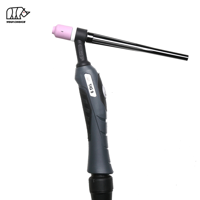
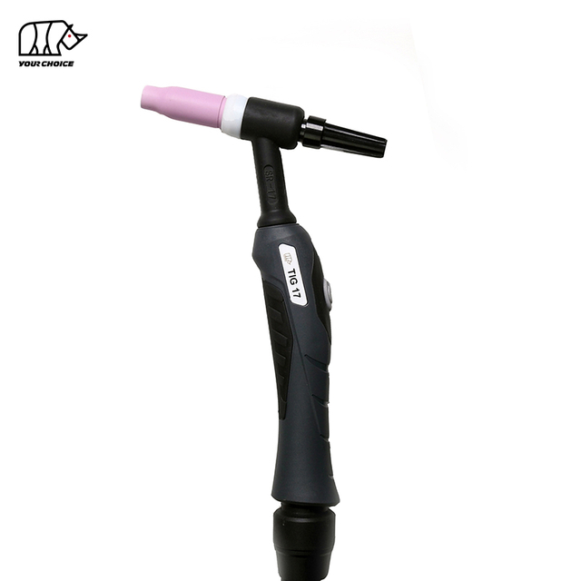
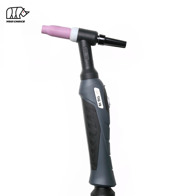
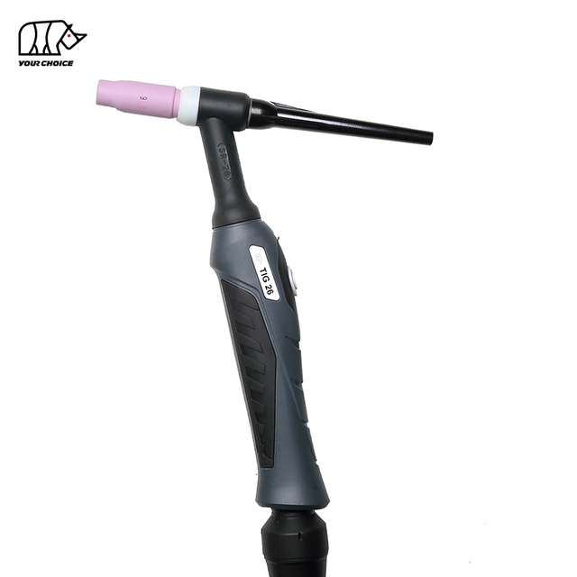
Verify consumable compatibility.TIG torch consumables are series-specific. A 9/20-series collet body is not interchangeable with a 17/18/26-series collet body, even if it appears to fit. Always specify the correct torch series when ordering replacement parts.
Clean threads before assembly. Metal debris on the collet body threads prevents full seating. Clean with a dry brush before assembly.
Problem 8: Porosity and Weld Contamination from Base Metal
What It Looks Like
The weld has scattered porosity (pinholes), black soot on the bead surface, or a rough, irregular bead profile on otherwise correctly set parameters. The problem is inconsistent — some sections weld cleanly, others do not.
Why It Happens
This problem differs from shielding gas porosity (Problem 5) in that the contamination originates from the workpiece rather than the torch or gas system.
Residual oil, grease, or drawing compound on tubing or sheet stock
Moisture trapped in oxide layers (especially common on aluminum)
Incomplete removal of mill scale, rust, or paint in the weld zone
Passivation chemicals or cleaning agents not fully rinsed from stainless steel
Galvanized or zinc-coated material — zinc vaporizes violently in the arc
Solution
Degrease before any other cleaning step. Apply acetone or a dedicated metal degreaser to a clean cloth and wipe the weld area. Never use a contaminated rag — you will transfer contamination rather than remove it.
Brush after degreasing. Use a dedicated stainless steel wire brush (one brush per material — never use a brush that has touched mild steel on stainless or aluminum). Brushing after degreasing removes the surface oxide layer and any remaining particulate.
For aluminum: remove the oxide layer immediately before welding. Aluminum's oxide layer (aluminum oxide) melts at approximately 2,050°C — far above aluminum's melting point of 660°C — and will contaminate the weld if not removed. Use a fresh stainless steel brush, then weld promptly.
For galvanized or coated material: remove the zinc coating from the weld zone mechanically (grinding) before welding. Never TIG weld over zinc-coated surfaces — the zinc fumes are hazardous and the weld quality will be unacceptable.
Store filler rods correctly. Filler rods accumulate surface contamination in storage. Wipe each rod with an acetone-dampened cloth before use. Store unused rods in their original packaging or a sealed tube.
Problem 9: Weld Crater Cracking
What It Looks Like
A visible crack appears at the end of the weld bead — specifically in the crater (the depression left when the arc is extinguished). The crack may be immediately visible or may appear only after the weld cools.
Why It Happens
Crater cracking is a solidification phenomenon. When the arc is abruptly terminated, the weld pool shrinks as it solidifies. If the crater is not adequately filled before solidification, the shrinkage stresses exceed the strength of the partially solidified metal, and a crack forms.
Abrupt arc termination without filling the crater
High-alloy or high-carbon base metals that are more susceptible to hot cracking
Amperage not tapered down before extinguishing the arc
Welding without a foot pedal or torch-mounted amperage control (no ability to reduce current at end of pass)
Solution
Use crater fill function. Most modern TIG welders include a dedicated crater fill mode that automatically ramps down current at arc termination, giving the welder time to add filler and fill the crater before the arc extinguishes.
Use a foot pedal or thumb controller. Manually reduce amperage gradually at the end of the weld pass. As current decreases, continue adding filler rod to maintain a full puddle until the arc is extinguished.
Run off onto a run-off tab. For critical welds, terminate the weld on a steel tab tack-welded at the end of the joint. The crater forms on the disposable tab, and the primary weld ends cleanly. Remove the tab after welding.
Increase preheat for crack-susceptible alloys. High-carbon steels, tool steels, and certain stainless grades are more prone to crater cracking. Preheat reduces thermal gradients and slows the cooling rate through the crack-susceptible temperature range.
Problem 10: Torch Body Damage — Cracked Nozzle, Damaged Back Cap, or Failed Power Cable
What It Looks Like
Visible cracks in the ceramic gas cup (nozzle). A back cap that will not seal or leaks gas. The torch power cable is stiff, kinked, or shows heat damage. Intermittent loss of power, gas, or both during welding.
Why It Happens
Ceramic nozzles are brittle and crack when dropped, struck, or thermally shocked by contact with the weld pool
Back caps develop thread damage from repeated removal, cross-threading, or being used as a handle to carry the torch
Power cables fatigue at the strain relief point (where the cable enters the torch handle) from repeated bending
Water-cooled torch hoses develop micro-cracks or fitting leaks from flexing and UV exposure over time
Heat damage to the cable insulation from contact with the workpiece or spatter
Solution
Inspect the gas cup (nozzle) before every session. A hairline crack in the ceramic is enough to disrupt gas flow asymmetrically, causing inconsistent shielding and porosity. Ceramic cups are inexpensive consumables — replace at the first sign of cracking.
Consider upgrading to a glass or pyrex cup. Clear glass nozzles allow direct visibility of the tungsten tip and puddle, and they are more impact-resistant than standard ceramic. They are particularly popular for precision work on thin material.
Handle the back cap with care. Always remove and replace the back cap by rotating it on the threads — never apply lateral force. Inspect threads periodically for damage. A back cap with damaged threads will never seal the gas circuit reliably.
Inspect the power cable at the strain relief. Flex the cable near the torch handle entry point — cracking insulation, unusual stiffness, or visible internal wire damage means the cable needs replacement. A damaged cable is both a fire and shock hazard.
Do not use the torch body as a hook or hang point. Many cable failures originate from mechanics hanging the torch by the cable or wrapping it tightly around fixtures. Hang torches from a proper torch hook or lay them flat.
Replace the full cable assembly when in doubt. On water-cooled torches, a failing coolant hose inside the cable can cause both electrical arcing and coolant leakage. If the torch is performing erratically and all consumables have been eliminated as the cause, cable replacement is the next step.
Quick-Reference Diagnostic Table
Problem
Key Symptom
Most Likely Cause
First Action
Tungsten contamination
Balled / dark tip, black weld spots
Dipped tungsten, short post-flow
Re-grind tungsten; increase post-flow
No arc / hard start
HF fires, arc won't transfer
Loose collet, wrong tungsten prep
Tighten collet; re-grind tip
Arc wandering
Arc jumps, uneven bead
Circumferential grind marks
Regrind longitudinally
Tungsten burns fast
Rapid tip melt-back
Wrong polarity or amperage too high
Check DCEN; reduce amps or upsize tungsten
Porosity / gas issues
Pinholes, dark bead, sugaring
Gas leak, flow rate wrong, short pre-flow
Soap-test all connections; adjust flow
Torch overheating
Hot handle, burning smell
Over-duty-cycle, loose connections
Reduce duty cycle; tighten assembly
Loose / slipping tungsten
Arc unstable, tungsten drops back
Worn collet or wrong size
Replace collet and collet body
Contamination from workpiece
Soot, irregular bead, inconsistent
Oil, oxide, moisture on base metal
Degrease and brush before welding
Crater cracking
Crack at weld end point
Abrupt arc termination
Use crater fill; taper current with pedal
Cracked cup / cable damage
Gas loss, intermittent power
Impact on ceramic, cable fatigue
Replace nozzle; inspect and replace cable
How to Build a Preventive Maintenance Routine for Your TIG Torch
The best approach to TIG torch problems is to prevent them before they disrupt production. A consistent maintenance routine takes less than five minutes before each session:
Before welding:
Inspect the gas cup for cracks or chipping.
Check tungsten condition — re-grind if contaminated or blunted.
Verify the collet and collet body are firm with no tungsten wobble.
Check the back cap threads and seal condition.
Confirm gas connections are tight. Run a brief pre-flow and listen for hissing at joints.
For water-cooled systems: verify coolant level and pump operation before striking an arc.
After welding:
Allow post-flow gas to run until the tungsten tip is no longer glowing.
For water-cooled torches, leave the coolant pump running for 2–3 minutes after arc-off to dissipate residual heat.
Store the torch on a hook or holder — never coil the cable tightly or wrap it around the machine.
Replace any consumable showing visible wear before the next session rather than carrying over a marginal part.
Selecting the Right TIG Torch for the Job
Many torch problems are not caused by defects or improper technique — they arise because the torch is the wrong specification for the application.
If your air-cooled torch consistently runs hot, consumables wear prematurely, and you regularly weld above 150 A with short rest intervals, the solution is almost always a water-cooled torch — not a parameter change or consumable upgrade.
Frequently Asked Questions
Q1: How often should I replace TIG torch consumables? There is no fixed interval — it depends entirely on amperage, duty cycle, and material. As a practical guide: inspect the collet and collet body every 20–40 hours of arc time; replace when you see oval wear on the collet bore, scoring inside the collet body, or any tungsten slippage. Gas cups should be replaced at the first crack. Tungsten is re-ground as needed rather than replaced on a schedule.
Q2: Can I use any tungsten in any TIG torch? Any tungsten of the correct diameter for the collet will physically fit, but performance varies significantly by type. For DC welding on steel and stainless, 2% lanthanated or 2% ceriated tungsten outperforms pure tungsten by a wide margin in arc stability and service life. For AC welding on aluminum, a zirconiated or pure tungsten is preferable because it forms and maintains a clean ball tip better than rare-earth grades.
Q3: What is a gas lens and should I always use one? A gas lens is a collet body replacement that incorporates a layered wire mesh screen to produce laminar (smooth, non-turbulent) gas flow. It provides superior shielding coverage, especially at longer arc lengths and in flat or overhead positions. It is not mandatory for basic work, but it is strongly recommended for welding stainless steel, titanium, or any application where oxidation control is critical. Gas lens setups also allow the use of larger-diameter cups, further improving coverage.
Q4: Why does my TIG weld look perfect on one side but have porosity on the other (back side)? This is back-side oxidation, most commonly seen on stainless steel and titanium. These materials require back-purging — flowing an inert gas (typically argon) along the back side of the joint to displace oxygen while the weld pool is molten and cooling. Without back purging, even a perfect front-side weld will show oxidation (sugaring) on the root, which compromises corrosion resistance and mechanical properties.
Q5: My TIG torch hisses or leaks gas but all external fittings seem tight. Where else should I check? Internal gas leaks are common and easy to miss. Check the O-ring inside the back cap — this small seal is responsible for closing the gas circuit at the rear of the torch. A cracked or flattened O-ring will leak gas backward. Also check the gas passage holes in the collet body for blockage or deformation, and inspect the torch body itself for hairline cracks in the insulating material around the gas ports.
Q6: How do I know if my TIG torch problem is the torch or the welding machine? A reliable diagnostic method: swap in a known-good torch if one is available. If the problem disappears, the issue is with the original torch. If the problem persists, the welder itself is the source. Common machine-side issues that mimic torch problems include: HF start capacitor failure (intermittent arc start), gas solenoid failure (no gas flow at the torch despite correct regulator settings), and welding current instability from a failing output stage.
Q7: What is the correct post-flow time for TIG welding? Post-flow time depends on amperage. A widely used rule of thumb is one second of post-flow for every 10 amperes of welding current. For example, welding at 150 A requires approximately 15 seconds of post-flow. For titanium, post-flow must be extended until the metal is below its oxidation threshold (approximately 400°C / 750°F) — this can require 30+ seconds at high amperages, or the use of a specialized trailing gas shield.
Conclusion
TIG welding torch problems range from straightforward consumable issues — a worn collet, a cracked nozzle, a contaminated tungsten — to more complex system failures involving gas circuits, power cables, or cooling systems. In nearly every case, the root cause is identifiable and the solution is both practical and achievable without specialized diagnostic equipment.
The ten problems covered in this guide account for the overwhelming majority of TIG torch issues encountered in real-world fabrication environments. By understanding what each symptom indicates, building a consistent pre-weld inspection habit, and matching the torch specification to the application, you can eliminate most torch-related downtime entirely and maintain the precision and cleanliness that make TIG welding the preferred process for critical applications.
A well-maintained TIG torch, loaded with the correct consumables and operated within its rated parameters, is one of the most reliable tools in any welding shop. The problems only arise when the basics are neglected — and the basics, as this guide shows, are entirely within your control.
This website uses cookies and similar technologies (“cookies”). Subject to your consent, will use analytical cookies to track which content interests you, and marketing cookies to display interest-based advertising. We use third-party providers for these measures, who may also use the data for their own purposes.
You give your consent by clicking "Accept all" or by applying your individual settings. Your data may then also be processed in third countries outside the EU, such as the US, which do not have a corresponding level of data protection and where, in particular, access by local authorities may not be effectively prevented. You can revoke your consent with immediate effect at any time. If you click on "Reject all", only strictly necessary cookies will be used.
 English
 简体中文
简体中文 العربية
 Français
 Русский
 Español
 Português
 Deutsch
 italiano
 日本語
日本語 한국어
한국어 Nederlands
 Tiếng Việt
 ไทย
ไทย Polski
 Türkçe
 ភាសាខ្មែរ
 Bahasa Melayu
 Filipino
 Bahasa Indonesia
 magyar
 Română
 Čeština
 Монгол
 қазақ
қазақ Српски
 हिन्दी
 فارسی
فارسی Slovenčina
 Slovenščina
 Norsk
Norsk Svenska
 українська
 Ελληνικά
 Suomi
Suomi Latine
 Dansk
Dansk বাংলা
বাংলা Hrvatski
 Afrikaans
 Gaeilge
 Eesti keel
 नेपाली
 Oʻzbekcha
 latviešu
 Azərbaycan dili
 Беларуская мова
 Bosanski
 Български
 ქართული
 Lietuvių